
CX31-P Polarized Light Microscope Configuration
The polarized light microscope is designed to observe and photograph specimens that are visible primarily due to their optically anisotropic character. In order to accomplish this task, the microscope must be equipped with both a polarizer, positioned in the light path at some position before the specimen, and an analyzer (a second polarizer), placed in the optical pathway between the objective rear aperture and the observation tubes or camera port.
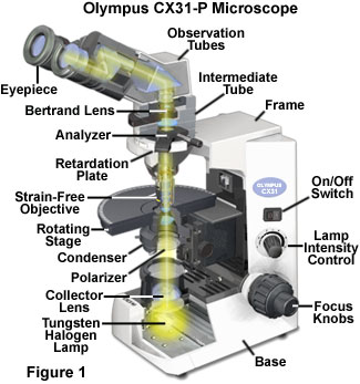
Image contrast arises from the interaction of plane-polarized light with a birefringent (or doubly refracting) specimen to produce two individual wave components that are polarized in mutually perpendicular planes. The velocities of these components are different and vary with the propagation direction through the specimen. After exiting the specimen, the light components become out of phase with each other, but are recombined with constructive and destructive interference when they pass through the analyzer.
Polarized light microscopy is utilized to distinguish between singly refracting (optically isotropic) and doubly refracting (optically anisotropic) media. Anisotropic substances, such as uniaxial or biaxial crystals, oriented polymers, or liquid crystals, generate interference effects in the polarized light microscope, which result in differences of color and intensity in the image as seen through the eyepieces and captured on film, or as a digital image. This technique is useful for orientation studies of doubly refracting media that are aligned in a crystalline lattice or oriented through long-chain molecular interactions in natural and synthetic polymers and related materials. Additional applications of polarized light microscopy are stress-strain relationships in transparent singly refracting media (for example, glass) and the identification and characterization of a wide spectrum of anisotropic substances through their refractive indices and birefringence.
The Olympus CX31-P polarizing microscope, illustrated in Figure 1, is equipped with all of the standard recommended accessories for examination of birefringent specimens under polarized light. Although similar to the common brightfield microscope, the polarized light microscope includes additional components that are unique to instruments in this class. These include the polarizer and analyzer, strain-free objectives and condenser, a circular graduated stage capable of 360-degree rotation, and an opening in the microscope body or intermediate tube for a full wave retardation plate, quarter wavelength plate, quartz wedge, or Berek, de Sénarmont, or Bräce-Köhler compensators.
The microscope presented in Figure 1 is equipped with a binocular observation tube mounted on the standard intermediate attachment, which houses the selectable and focusable Bertrand lens, as well as a 180-degree rotatable analyzer, allowing both conoscopic and orthoscopic examination of birefringent specimens. The objectives (typically ranging in magnifications of 4x, 10x, 20x, 40x, and 100x) are of the strain-free low birefringence type optimized for polarizing light microscopy, and are mounted in specialized adapters that allow each to be individually centered. The circular 360-degree rotatable stage can be clamped at any rotation position and is also equipped with a centering function, as well as with an accessory mechanical positioning attachment that enables precise x-y translation of specimens.
Removal of the polarizer and analyzer from the light path, while maintaining the other component configuration, results in an instrument equivalent to a typical brightfield microscope with respect to the optical characteristics. Polarized light microscopy is a contrast-enhancing technique that improves the quality of images obtained with birefringent materials in comparison to other techniques such as darkfield and brightfield illumination, differential interference contrast, phase contrast, Hoffman modulation contrast, and fluorescence, in addition to providing qualitative and quantitative information about the optical properties of the specimen.
Microscope Body
Typical modern polarizing (and brightfield) microscopes (Figure 1) incorporate an illuminator, which utilizes a 20 to 100-watt high-energy tungsten-halogen lamp, either mounted in a lamphouse or as an integral part of the microscope base (see Figure 1). The Olympus CX31-P is equipped with an integral 6-volt, 30-watt halogen lamp, with a mounting mechanism that guarantees pre-focused and pre-centered alignment. A transformer providing direct current (DC) voltage to the lamp is built directly into the microscope base and is controlled by a potentiometer positioned near the lamp switch in the microscope body (the lamp voltage control; Figure 1). Accessory filters, such as those for light attenuation and color correction, may be attached to the top of the light exit port on the microscope base. Also built into the microscope base as part of the primary illumination pathway of the microscope are a collector lens, the field iris aperture diaphragm, and a first-surface reflecting mirror that directs light through the port positioned directly beneath the condenser. These components control the light distribution, size, and intensity of the illumination field. The microscope frame is designed to be vibration free and to provide the optimum light source for Köhler illumination. In general, the modern microscope illumination system is capable of providing controlled light to produce an even, intensely illuminated field of view, even though the lamp emits only a highly variable discontinuous spectrum of visible, infrared, and near-ultraviolet radiation.
The precision and stability of the microscope stage is critical in polarized light techniques, and modern rotating stages greatly facilitate accurate measurements of specimen birefringence properties. The CX31-P includes a circular rotating stage (Figure 1), which provides 360-degree rotation and can be fixed in any position using a knurled locking screw. The stage is graduated in 1-degree increments and is equipped with a vernier scale for greater precision, which allows retardation measurements to be made with a minimum resolution of 6 minutes of arc. Centering adjustments are provided, which in conjunction with objective centering adapters, allow the stage center of rotation, illumination axis, and each objective to be precisely aligned on a common optical axis. An optional mechanical stage adapter may be attached that provides accurate specimen positioning along two orthogonal axes (x-y translation). Dual scales, with verniers, allow reproducible specimen positioning within a range of approximately 4 centimeters along each axis. A variety of specimen holder and slide designs can be accommodated by the clamping mechanism, and the graduated scales permit stage translation in controlled increments, as well as enabling recorded x-y positions to be reset following stage movement.

Polarized light microscopy requires a condenser that is similar to that used in conventional brightfield microscopy, typically an achromat with a numerical aperture between 0.90 and 1.35. However, it is important that condensers designed for polarized light microscopy employ strain-free optics to avoid altering the polarization properties of the transmitted light. It is common for such condensers to employ a swing-out top lens that is moved into position to provide adequate illumination and appropriate numerical aperture for conoscopic observation with high-numerical-aperture objectives. This lens is removed from the optical path for low-magnification observation in orthoscopic mode. An alternative is to utilize a long-working-distance condenser without the auxiliary swing-in lens, which serves for both orthoscopic specimen survey and to provide the high illumination level and numerical aperture required for conoscopic observation of birefringent specimens. The CX31-P polarizing microscope employs a strain-free UIS (Universal Infinity System) Abbe condenser of the latter type, which incorporates a twelve-blade aperture iris diaphragm that is adjusted through movement of a sliding lever (Figure 2). The condenser is centerable and focusable, with a numerical aperture specification of 1.25 for oil immersion, and 0.9 in air. A scale adjacent to the diaphragm adjustment lever indicates the approximate condenser numerical aperture corresponding to the lever position, ranging from 0.1 to 1.0 and higher.
In a majority of the common microscope configurations, the polarizer (Figure 1) is positioned either at the light port in the microscope base or in a filter holder directly beneath the condenser. The CX31-P model illustrated in Figure 1 is equipped with a rotating polarizer assembly that is directly attached to the bottom of the condenser. A short tube assembly holding the polarizing filter slides into the lower condenser barrel, and is held firmly by a spring-loaded ring, allowing free rotation of the filter about the optical axis. The polarizer can be rotated through a full 360 degrees and is easily detached, when maximum intensity is desired for brightfield observation, by simply pulling it away from the condenser-aperture diaphragm assembly.
The remaining functional components of the microscope body are the focusing mechanism and the revolving nosepiece turret, which facilitates rapid objective changes during specimen observation (see Figure 1). The CX31-P polarizing microscope utilizes a quadruple revolving nosepiece mounted to a rigid fixed arm of the microscope frame (focusing being accomplished by stage rather than objective movement). The nosepiece accommodates up to four objectives, with or without the centering adapters, and its plane of rotation is inclined in order to minimize interference between the objectives not being used and the specimen area. The focusing mechanism is a rack and pinion assembly that provides a total stage movement of 25 millimeters, controlled through concentric coarse and fine focus knobs located on either side of the lower microscope body (Figure 1). The right hand fine-focus knob is marked with graduations around its full circumference, with the minimum interval corresponding to a stage movement of 2.5 micrometers.
Intermediate Tube
Light that is diffracted, refracted, and transmitted by the specimen converges at the rear focal plane of the objective and is then directed to an intermediate tube (illustrated in Figure 3), which houses a second polarizer, typically termed the analyzer. The intermediate tube also accommodates the attachment of observation and/or photographic systems that form an image by transformation of the diffraction information. In order to operate in the common "crossed-polars" optical configuration for evaluation of specimen birefringence properties, the analyzer must be oriented with its direction of light vibration at a 90-degree angle to the vibration axis of the polarizer mounted on the condenser. By convention, the vibration direction of the polarizer is generally set to the East-West orientation (abbreviated E-W), dictating that the analyzer is positioned with its vibration direction in a North-South (abbreviated N-S) orientation.
The standard configuration of the CX31-P microscope includes a conoscopic intermediate tube that houses the rotatable analyzer, a Bertrand lens (Figures 1 and 3) that is inserted or removed from the optical path for changeover between orthoscopic and conoscopic observation modes, and also provides a slot for insertion of retardation plates, compensators, and other accessories. The dimensions of this opening follow the DIN standard (20 × 6 millimeters, width × thickness), and the slot accommodates any of eight Olympus DIN style compensators and accessory plates provided for polarizing microscopy. The Bertrand lens is incorporated into the tube assembly, and swings laterally in and out of position within the body of the intermediate tube (see Figure 3). It is focusable by means of a small knurled knob, and can be removed from the assembly.
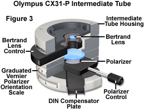
Polarizing microscopy requires that the analyzer be positioned after the specimen in the optical path, in order to allow determination of the nature and degree of modification that the specimen imposes on the already-polarized illuminating beam. On most microscopes, the analyzer is positioned either in a slot directly above the objective or in the intermediate tube between the objective nosepiece and the observation tubes. The standard conoscopic intermediate tube used on the CX31-P microscope incorporates a detachable and rotatable analyzer that is moved into and out of the light path by means of a sliding rod mechanism. The analyzer segment of the intermediate tube is rotatable through 180 degrees, and can be fixed at any position by tightening a knurled locking knob. An inscribed scale, marked at 2-degree increments, indicates the rotation position, and in combination with the vernier scale, a minimum polarization retardation of 6 minutes can be measured.
The accessory slot of the intermediate tube accommodates a full range of eight Olympus-provided compensators, two of the plate variety for introducing a fixed retardation level, and six different measuring compensators, which are adjustable to produce various degrees of retardation. Each of the plates and variable compensators are utilized to produce a specific optical path length difference (OPD) between mutually perpendicular plane-polarized light waves when inserted diagonally in the microscope between crossed polarizers. The compensator slot of the CX31-P intermediate tube provides simple, reproducible positioning of this type of accessory in the required geometric orientation relative to the polarizer and analyzer when these are properly aligned in N-S and E-W directions, according to convention. The central location, at the intermediate tube, of the controls for manipulating the Bertrand lens, inserting, removing and rotating the analyzer, and implementing a variety of compensator attachments greatly enhances the operational ease of the CX31-P configuration.
In addition to the standard conoscopic intermediate tube, the CX31-P microscope can be equipped with two other available intermediate attachments for orthoscopic and conoscopic observation. One of these is a polarizing intermediate attachment that accommodates a special analyzer designed for performing gout screening in medical diagnostic settings. These components are also applicable in studies of living cells in muscle tissues, and for performing various urinary and other clinical determinations as well as for the identification of amyloid in metabolic studies. The same intermediate tube accepts an optional plate adapter that can be utilized for a variety of functions, including positioning an accessory analyzer for transmitted light, and for accommodation of any DIN style compensator. The third intermediate tube designed for the CX31-P allows only orthoscopic observation and accepts a slide-in analyzer attachment for polarized light that provides a full 360-degree rotation by manipulation of a graduated knob located on the protruding portion of the attachment when it is inserted into the intermediate tube slot. This tube can be stacked onto intermediate tubes having DIN compensator slots in order to conduct quantitative measurements.
The eight Olympus compensators that are compatible with the CX31-P microscope include quarter wave and full wave fixed-retardation plates, a quartz wedge, a de Sénarmont compensator, two Bräce-Köhler compensators, and two Berek compensators. The characteristics of the entire range of compensators are summarized in Table 1. Each of the available retardation plates and measuring compensators conform to standardized DIN dimensions, and consequently can be interchanged among other microscopes that follow the same standard. The full wavelength retardation plate (sometimes referred to as a tint plate or first-order red plate) is of the appropriate thickness to produce an optical path length difference between the two mutually perpendicular plane-polarized light waves of a full wavelength (specifically 530 nanometers). This full-wavelength retardation corresponds to a first-order red interference color (as illustrated in the Michel-Levy chart). The full wave plate is commonly used to enhance the contrast of weakly birefringent specimens, and to determine the optical sign of birefringent crystals by observing the nature of the effect of additional retardation on the specimen interference colors or interference figures (observed in conoscopic mode).
Quarter wave retardation plates introduce a relative phase shift of 90 degrees between the two orthogonal wavefront components of transmitted linearly polarized light. This phase shift between the ordinary and extraordinary rays results in the conversion of linearly polarized light into circularly or elliptically polarized light and vice versa. In addition to this capability of polarization OPD conversion, the quarter wave plate is useful for qualitatively assessing the birefringent properties of materials including the relative degree of birefringence between different specimens or in comparison to standard specimens with known properties. Quarter wave plates are typically designed to introduce between 137 and 150 nanometers of retardation; the quarter wave plate provided for the Olympus CX31-P has a specification of 137 nanometers.
The simplest variable compensator is the quartz wedge, which is mounted so that the changing thickness along the length of the wedge can be utilized to produce a range of retardation values as the wedge is moved into and out of the optical path of the microscope. By observing changes in polarization properties of birefringent specimens as the wedge thickness in the light path is varied, approximate specimen retardation values can be determined. The accessory wedge for the CX31-X provides a retardation range of 4 wavelengths (4λ), from 550 to 2200 nanometers. The de Sénarmont compensator utilizes a precisely fabricated quarter wavelength plate in combination with the rotating analyzer to make extremely accurate retardation measurements over a 0 to 546-nanometer range (1λ). Precise optical path difference determinations require monochromatic illumination matching the compensator design wavelength, and a narrowband interference filter is typically used with tungsten-halogen lamps to produce the required wavelength. The de Sénarmont compensator is useful for quantitative analysis of retardation in crystals and living organisms, and for optical strain studies, as well as for enhancing image contrast in weakly birefringent specimens that are difficult to examine under crossed-polar illumination.
Compensator Characteristics
| Plate Type | Optical Path Difference (Nanometers) |
Comments |
|---|---|---|
| Full Wavelength | 530 | First-Order Red Contrast Enhancement Optical Sign Determination |
| Quarter Wavelength | 137 | Linear-Circular Polarization Conversion Birefringence Evaluation |
| Quartz Wedge | 550-2200 | Approximate Retardation Measurement Four-Wavelengths Range |
| de Sénarmont | 0-546 | Retardation Measurement Contrast Enhancement |
| Berek | 0-1640 | Retardation Measurement Three-Wavelengths Range |
| Thick Berek | 0-11000 | High-Retardation Measurement Twenty-Wavelengths Range |
| Brace-Köhler | 0-55 | Low-Retardation Measurement One-Tenth Wavelength Range |
| Brace-Köhler | 0-20 | Contrast Enhancement One-Thirtieth Wavelength Range |
Table 1
For retardation measurements over a larger range, the two Berek compensators employ adjustable-tilt birefringent plates of different thickness to provide either 3λ or 20λ (with a thicker plate) optical path difference ranges (referred to 546-nanometer green light). Retardation level determinations of crystals, macromolecules, fibers, and living organisms can be made with the standard Berek compensator between zero and 1640 nanometers, while the thick Berek compensator is applicable to high retardation levels over the range of zero to 11000 nanometers. The two available Bräce-Köhler compensators utilize compensator crystals that can be precisely rotated mechanically about the microscope optical axis to measure extremely small retardation levels.
Very low values of birefringence are sometimes encountered in living organisms, thin films, and glasses exhibiting low strain birefringence, for example. One of the Bräce-Köhler compensators is adjustable over a range of one-tenth wavelength (0 to 55 nanometers) for determining low retardation levels. The smallest-range compensator covers a range of 0 to 20 nanometers (one-thirtieth of a wavelength), and is most often used to produce a usable level of contrast in crystals, macromolecules, fibers and fiber bundles with minute birefringence levels. This type of compensator is capable, in general, of measuring retardation values of a few tenths of a nanometer with monochromatic 546-nanometer light, or less than one-thousandth of a wavelength.
Observation Tubes and Eyepieces
Four different observation tubes can be chosen when configuring the CX31-P polarizing microscope, differing in their options for recording images, and in their field width specifications and other features. Two binocular observation tubes are available, one having a field number of 20, and one with a wider viewfield corresponding to a field number of 22. Eyepieces having appropriate field numbers are available for either binocular tube. Although binocular tubes are primarily intended for visual observation, an eyepiece adapter designed to allow mounting an Olympus Camedia series digital camera provides a cost-effective means of capturing digital images of very high quality. The preferred method for efficient and convenient imaging through the microscope is through the use of a trinocular observation tube that transmits a portion of the light from the specimen to an imaging system, allowing simultaneous binocular viewing and image recording. Two trinocular tube designs provide the same field width differences as the binocular tubes, and each must be utilized with the appropriate compatible eyepieces (field numbers of either 20 or 22).
Either of the available CX31-P trinocular observation tubes provides a third light pathway that makes it possible to attach a straight single-port photographic tube or a video adapter, for cameras such as the dedicated DP12 digital microscope camera, without interfering with binocular specimen observation. Typically, trinocular tubes employ beamsplitters to partition the image-forming light between the eyepieces and the photographic light path. The relative proportion of light delivered to each optical path may be fixed, or alternatively, various user-selectable settings may be provided, which are selected by a lever or other control that repositions the beamsplitting components within the observation tube. These features differ for the two Olympus trinocular tube options.
One trinocular observation tube model offers the wider viewfield width (field number 22), and includes a sliding three-position control for selecting the relative proportion of light delivered to the binocular observation tubes and the single-port phototube. The selector positions correspond to the following percentage ratios for light sent to the binocular observation path relative to light diverted to the image capture tube (binocular : phototube): 100:0 / 20:80 / 0:100. The first beamsplitter setting transmits 100 percent of the light from the specimen to the observation tubes, the second position transmits 20 percent to the observation tubes and 80 percent to the phototube (allowing simultaneous viewing and image capture), and the third position diverts 100 percent of the light to the accessory phototube for maximum image capture efficiency. The alternate trinocular observation tube available for the CX-31P microscope has a field number of 20, and a fixed proportional split of 50 percent to each of the observation and image capture optical paths (50:50), allowing simultaneous viewing and photography.
A Filar micrometer eyepiece can be used with the binocular or trinocular tubes and a crossline reticle eyepiece is available for the wider-field models. A newly developed binocular assembly eliminates the potential problem of changes in the angle of the crossline reticle when the interpupillary distance is adjusted. This typical annoyance is a significant problem in polarizing microscopy, in which specimen feature and/or optical axis orientations relative to the polarizer and analyzer axes are being evaluated. Maintaining the intended crossline orientation (usually N-S and E-W) facilitates precise alignment of the polarization oscillation directions, which is essential for accurate measurements of retardation and other optical properties.
Objectives
Suitable objectives for polarized light microscopy are available with varying degrees of optical correction, and include achromats, plan achromats, and plan fluorites. Regardless of the extent of aberration correction, an essential requirement is that the objective optical elements be free of residual strain that might result in internal birefringence of the objective contributing to the apparent specimen interference. When both the objectives and condenser are strain-free, the microscope viewfield appears a deep uniform black when viewed with crossed polarizers and with no specimen in the light path. In addition to strain birefringence, inherent natural birefringence, due to the anisotropic character of materials used to make the lens elements, can be present in objectives that are not specifically designed to be used with polarized light. Any appreciable residual internal birefringence will manifest itself by producing a blue, gray, or brownish background under crossed polarizers, rather than the expected deep black, and can make interpretation of polarized-light images very difficult. The revolving nosepiece of the CX31-P microscope accommodates mounting of optional centering adapters (see Figure 4) between the nosepiece and objective that allow each objective to be independently centered on the instrument optical axis. Although this alignment is not essential, when each objective and the rotating stage are centered on a common axis, polarized light observations can be made much more easily and efficiently, and magnification changes can be rapidly effected without shifts in the viewfield.

Two series of Olympus objectives are recommended for optimum performance with the CX31-P polarizing microscope, the ACH-P and UPLFl-P (Figure 4) series. Objectives of both groups are high-performance strain-free components belonging to the UIS (Universal Infinity System) category of infinity-corrected optics. Configuration with ACH-P series objectives offers cost-effective polarized light capabilities ideally suited to clinical applications and student training. As indicated by their designation, these objectives are achromats (ACH) suitable for polarized light applications (P), and are available with magnification factors of 10x, 20x, 40x, and 100x (oil immersion). For lower-magnification polarized-light observation, a 4x plan achromat (PL4XP) is available, which provides excellent correction for field flatness up to field number 22, a highly desirable property for uses such as clinical survey inspections.
The highest level of performance is provided by objectives in the UPLFl-P series, which have the fluorite category (Fl) designation that is assigned to semi-apochromat objectives with nearly complete elimination of optical aberrations. These objectives exhibit high extinction properties and high contrast, making them suitable for precise polarized light measurements, such as those performed on very slightly birefringent substances in combination with a Bräce-Köhler compensator. The UPLFl-P series objectives are designed for a wide viewfield (field number 26.5) and a high degree of correction for field flatness, indicated by the PL (plan) designation. In addition, these universal (U) objectives can be employed in brightfield and DIC (differential interference contrast) observation modes, and for fluorescence techniques employing visible and ultraviolet excitation if the polarized light intermediate tube is removed from the CX31-P. Compared to the ACH-P series, the UPLFl-P objectives have shorter working distances, but benefit from higher numerical aperture across the magnification range. Aside from the usual gains in resolution and contrast, the larger acceptance angle of high numerical aperture objectives is a significant advantage in the conoscopic observation mode. The numerical aperture values are 0.13, 0.30, 0.50, 0.75, and 1.30 for the (UPLFl-P) 4x, 10x, 20x, 40x, and 100x oil immersion optics, respectively.
The model CX31-P polarizing microscope provides the versatility to be configured for nearly any research application requiring high quality imaging and advanced precision measurement capabilities of specimen properties resulting from optical anisotropy. It also is sufficiently cost-effective, and provides mechanical stability and durability to meet the demands of student training, routine laboratory inspection, and clinical diagnostic settings. The flexibility in configuration, and the compatibility with optics of the highest quality, and with standardized interchangeable measuring accessories, allows the CX31-P to be employed in a full range of applications, including the evaluation of the birefringence properties of tissues and living organisms, as well as complex analyses of macromolecules, materials, rocks, minerals, and fibers.