Introduction to Phase Contrast
The search was still on in the 1930's to find a way of using both direct and diffracted light from all azimuths to yield good contrast images of unstained objects that do not absorb light. Research by Frits Zernike during this period uncovered phase and amplitude differences between zeroth order and deviated light that can be altered to produce favorable conditions for interference and contrast enhancement.

Unstained specimens that do not absorb light are called phase objects because they slightly alter the phase of the light diffracted by the specimen, usually by retarding such light approximately 1/4 wavelength as compared to the undeviated direct light passing through or around the specimen unaffected. Unfortunately, our eyes as well as camera film, are unable to detect these phase differences. To reiterate, the human eye is sensitive only to the colors of the visible spectrum (variations in light frequency) or to differing levels of light intensity (variations in wave amplitude).
In phase specimens, the direct zeroth order light passes through or around the specimen undeviated. However, the light diffracted by the specimen is not reduced in amplitude as it is in a light-absorbing object, but is slowed by the specimen because of the specimen's refractive index or thickness (or both). This diffracted light, lagging behind by approximately 1/4 wavelength, arrives at the image plane out of step (also termed out of phase) with the undeviated light but, in interference, essentially undiminished in intensity. The result is that the image at the eyepiece level is so lacking in contrast as to make the details almost invisible.
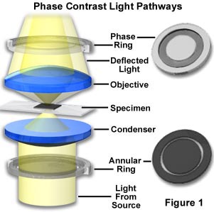
Zernike succeeded in devising a method--now known as Phase Contrast microscopy--for making unstained, phase objects yield contrast images as if they were amplitude objects. Amplitude objects show excellent contrast when the diffracted and direct light are out of step (display a phase difference) by 1/2 of a wavelength. Zernike's method was to speed up the direct light by 1/4 wavelength so that the difference in wavelength between the direct and deviated light for a phase specimen would now be 1/2 wavelength. As a result, the direct and diffracted light arriving at the image level of the eyepiece would be able to produce destructive interference (see the section on image formation for absorbing objects previously described). Such a procedure results in the details of the image appearing darker against a lighter background. This is called dark or positive phase contrast. A schematic illustration of the basic phase contrast microscope configuration is illustrated in Figure 1.
Another possible course, much less often used, is to arrange to slow down the direct light by 1/4 wavelength so that the diffracted light and the direct light arrive at the eyepiece in step and can interfere constructively. This arrangement results in a bright image of the details of the specimen on a darker background, and is called negative or bright contrast.

Phase contrast microscopy was very successful and ultimately gained widespread application, resulting in Zernike's award of the prestigeous Nobel prize in physics in 1953. The phase contrast technique has hailed as the greatest advance in microscopy in a century. Phase contrast, by "converting" phase specimens such as living material into amplitude specimens, allowed scientists to see details in unstained and/or living objects with a clarity and resolution never before achieved.
The Zernike method involves the separation of the direct zeroth order light from the diffracted light at the rear focal plane of the objective. To do this, a ring annulus is placed in position directly under the lower lens of the condenser at the front focal plane of the condenser, conjugate to the objective rear focal plane. As the hollow cone of light from the annulus passes through the specimen undeviated, it arrives at the rear focal plane of the objective in the shape of a ring of light. The fainter light diffracted by the specimen is spread over the entire rear focal plane of the objective.
If this combination were allowed, as is, to proceed to the image plane of the eyepiece, the diffracted light would be approximately 1/4 wavelength behind the direct light. At the image plane, the phase of the diffracted light would be out of phase with the direct light, but the amplitude of their interference would be almost the same as that of the direct light. This would result in very little specimen contrast.

To speed up the direct undeviated zeroth order light, a phase plate is installed with a ring shaped phase shifter attached to it at the rear focal plane of the objective. The narrow area of the phase plate is optically thinner than the rest of the plate. As a result, undeviated light passing through the phase ring travels a shorter distance in traversing the glass of the objective than does the diffracted light.
Now, when the direct undeviated light and the diffracted light proceed to the image plane, they are 1/2 wavelength out of phase with each other. The diffracted and direct light can now interfere destructively so that the details of the specimen appear dark against a lighter background (just as they do for an absorbing or amplitude specimen). This is a description of what takes place in positive or dark phase contrast.
If the ring phase-shifter area of the phase plate were to be made thicker than the rest of the plate, direct light is slowed by 1/4 wavelength. In this case, the zeroth order light arrives at the image plane in step (or in phase) with the diffracted light, and constructive interference takes place. The image would appear bright on a darker background. The image appears bright on a darker background. This type of phase contrast is described as negative or bright contrast.
Because the undeviated light of the zeroth order is much brighter than the faint diffracted light, a thin absorptive transparent metallic layer is deposited on the ring to bring the direct and diffracted light into better balance of intensity in order to increase contrast. Also, because the speeding up or slowing down of the direct light is calculated on a 1/4 wavelength of green light, the phase image will appear best when a green filter is placed in the light path (a green interference filter is preferable). Such a green filter also helps achromatic objectives produce their best images, since achromats are spherically corrected for green light.
The accessories needed for phase contrast work are a substage phase contrast condenser equipped with annuli and a set of phase contrast objectives, each of which has a phase plate installed. The condenser usually has a brightfield position with an aperture diaphragm and a rotating turret of annuli (each phase objective of different magnification requires an annulus of increasing diameter as the magnification of the objective increases). Each phase objective has a darkened ring on its back lens. Such objectives can also be used for ordinary brightfield transmitted light work with only a slight reduction in image quality.
Phase Plate/Ring Alignment

Practice aligning a phase contrast microscope and discover how improper alignment affects specimen appearance.
Start Tutorial »
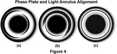
The phase outfit, as supplied by the manufacturer, usually includes a green filter and a phase telescope. The latter is used to enable the microscopist to alight the condenser annulus to superimpose it onto the ring of the phase plate. A set of centering screws in the substage condenser allows manipulation of the annulus to align it while observing the back focal plane of the objective with the phase telescope (or through a Bertrand lens).
To set up a phase microscope (cheek lining cells are a readily available test material), focus the specimen with the 10X phase objective. Next, configure the microscope for Köhler illumination using the brightfield (0) position of the condenser. This critical step is to assure the proper alignment of the microscope's objective, condenser, and field diaphragm. After the microscope is properly aligned, open up the condenser aperture diaphragm and swing the turret of the condenser into the 10 position (this usually automatically opens the aperture diaphragm). Place the green filter in the light path, and remove one of the eyepieces. Insert the phase telescope and, while observing the back of the objective, use the Annulus Centering Screws to center the annulus to the ring of the plate. A Bertrand lens or a pinhole eyepiece, if available, will allow a view of the back focal plane of the objective. Centering the phase annulus is often easier to do if the specimen is temporarily removed from the light path. After alignment of the phase ring with the annulus, reinsert the eyepiece and place the specimen back into its proper place on the microscope stage in the optical path.
Repeat the same procedure for each objective, making sure that the turret is rotated so the appropriate phase annulus is positioned to match the objective magnification. Some manufacturers provide individual push-in, centering, annuli that can be inserted into the lower part of the common Abbe condenser. Such inexpensive, simple devices do well with the 10X, 20X, and 40X phase objectives, but the condenser can receive only one at a time.
Phase microscopy continues to be a widely used and important tool, particularly for the microscopist studying living and/or unstained material, such as cells and tissues in culture. The method is also currently used simultaneously with reflected light fluorescence to reveal areas of a specimen that do not fluoresce. Phase microscopy techniques are particularly useful with specimens that are thin and scattered in the field of view.
There are some limitations of phase contrast microscopy:
- Phase images are usually surrounded by halos around the outlines of details. Such halos are optical artifacts, which sometimes obscure the boundaries of details.
- The phase annuli do limit the working numerical aperture of the optical system to a certain degree, thus reducing resolution.
- Phase contrast does not work well with thick specimens because of shifts in phase occur from areas slightly below or slightly above the plane that is in focus. Such phase shifts confuse the image and distort image detail.
- Phase images appear gray if white light is used and green if a green filter is used. In the past, many microscopists restricted their film to black and white when performing photomicrography on phase specimens. Today, many color films reproduce black, white, and grayscales very effectively, especially the tungsten-balanced transparency films from Fuji, Kodak, and Agfa.
Phase microscopy is another exemplification of how the manipulation of light at the substage condenser lower lens level and at the objective rear focal plane level has significant effect upon the image that is observed through the eyepiece.
