Fundamental Concepts in DIC Microscopy
Living cells and other transparent, unstained specimens are often difficult to observe under traditional brightfield illumination using the full aperture and resolution of the microscope objective and condenser system. Phase contrast, first developed by Frits Zernike in the 1930s, is often employed to image these challenging specimens, but the technique suffers from halo artifacts, is restricted to very thin specimen preparations, and cannot take advantage of the full condenser and objective apertures.
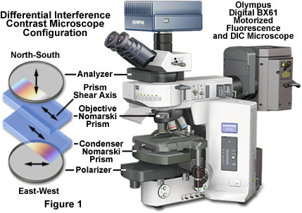
The basic differential interference contrast (DIC) system, first devised by Francis Smith in 1955, is a modified polarized light microscope with two Wollaston prisms added, one to the front focal plane of the condenser and a second at the rear focal plane of the objective (see Figure 1). Several years later, Georges Nomarski, a Polish-born French physicist, modified the standard Wollaston prism configuration to enable these exceedingly thin optical components to be physically located away from the aperture conjugate planes.
The optical components required for differential interference contrast microscopy do not mask or otherwise obstruct the objective and condenser apertures (as in phase or Hoffman modulation contrast), thus enabling the instrument to be employed at full numerical aperture. The result is a dramatic improvement in resolution (particularly along the optical axis), elimination of halo artifacts, and the ability to produce excellent images with relatively thick specimens. In addition, differential interference contrast produces an image that can be easily manipulated using digital and video imaging techniques to further enhance contrast.
Presented in Figure 1 is the typical differential interference contrast configuration for a modern transmitted light microscope also equipped for fluorescence illumination. The basic optical scheme closely resembles a traditional polarized light microscope retrofitted with specialized beamsplitting prisms. A polarizer and analyzer are inserted into the optical pathway before the condenser and after the objective, respectively. Several beamsplitting (modified Wollaston or Nomarski) prisms designed to accommodate objectives having differing focal lengths and aperture sizes are installed in the condenser turret assembly, while a single Nomarski prism (compatible with all objective specifications) resides in a slider frame positioned in the nosepiece. The relative optical orientation and sequential positioning of these auxiliary components is also indicated in the figure.
Unlike phase contrast, differential interference contrast converts gradients in specimen optical path length into amplitude differences that can be visualized as improved contrast in the resulting image. The specimen optical path difference is determined by the product of the refractive index difference (between the specimen and its surrounding medium) and the geometrical distance (thickness) traversed by a light beam between two points on the optical path. Images produced in differential interference contrast microscopy have a distinctive shadow-cast appearance, as if they were illuminated from a highly oblique light source originating from a single azimuth. Unfortunately, this effect, which often renders specimens in a pseudo three-dimensional relief, is frequently assumed by uninformed microscopists to be an indicator of actual topographical structure.
Differential interference contrast microscopy, unlike the situation with traditional double-beam interference instruments, is largely a qualitative rather than a quantitative technique. Specimens are sampled by two closely spaced partially coherent, but orthogonal, wavefronts separated by a distance that is slightly beneath the lateral resolution of the microscope. Because the sampling and reference beams both traverse a similar region of the specimen (and/or the surrounding medium), which is confined to a spatial separation distance of less than two micrometers, DIC will not yield accurate measurements of specimen refractive index or thickness. Instead, the technique is useful for determining the orientation of phase gradients and capitalizing on the full objective aperture to produce thin optical sections free of obscuring disturbances from specimen features positioned beyond the immediate focal plane.
The wave pairs employed in differential interference contrast are generated by the action of a birefringent beamsplitter (either a Wollaston or Nomarski compound prism) on a plane-polarized wavefront of coherent light originating from a tungsten filament and focused into the front focal plane of the microscope condenser (where the beamsplitter is positioned). When a pair of coherent light rays produced by the beamsplitter encounters a phase gradient, due to refractive index and/or thickness variations, each ray will become deformed and experience a slightly different optical path difference when traversing through the specimen. Upon emerging from the specimen, the rays will be unequal in phase. The difference in optical path is translated by the DIC microscope into a change in amplitude in the final image observed in the eyepieces. However, from simply examining the image, it is impossible to determine whether the phase gradient in the specimen occurs because of differences in refractive index or thickness (or both). This uncertainty is due to the fact that optical path difference is derived from the product of refractive index and thickness, and lacking independent information about either quantity, the origin of the difference cannot be ascertained.
After wavefronts generated by the beamsplitting prism pass through a specimen phase gradient, they are recombined through differential interference by a second prism and an analyzer (another polarizer) to yield a high-contrast rendition of the gradient. Both differential interference contrast and phase contrast rely on specimen phase differences between sampling and reference beams to produce an image based on varying amplitude. Phase contrast translates image amplitude information from the phase variations exhibited between light waves diffracted by the specimen and a reference beam passed through the condenser annulus, specimen, and phase plate. In distinction, however, the DIC image corresponds to the mathematical first derivative, rather than the magnitude, of the gradient profile obtained from the specimen optical path difference.
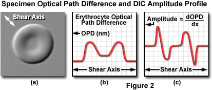
The relationship between optical path gradients and intensity profiles in DIC microscopy is illustrated in Figure 2. The specimen presented in Figure 2(a) is a doughnut-shaped human erythrocyte imaged at high magnification in differential interference contrast with the shear axis indicated by a double-headed arrow (northwest to southeast). A plot of the optical path difference (the ordinate) verses the diameter of the erythrocyte along the shear axis (the abscissa) is shown in Figure 2(b). Note that the optical path profile reflects the thin center and thick edges exhibited by human red blood cells. An intensity scan across the differential interference contrast image, which corresponds very closely to the first derivative of the optical path difference curve (Figure 2(b)) when added to a constant, is presented in Figure 2(c). Positive and negative slopes in the erythrocyte optical path profile generate regions of higher and lower amplitude, respectively, in the first derivative scan and corresponding differential interference contrast image. Regions of the optical path difference profile that exhibit no change in slope have the same intensity as the background and correspond to the baseline in the first derivative plot of the optical path difference.
Differential Interference Contrast Optical Configuration
Strategic placement of precisely matched optical components in (or near) conjugate planes and other specific locations within the microscope is essential to the configuration scheme for differential interference contrast (see Figure 1). All of the major manufacturers provide high-quality, precision DIC optical accessories, often marketed in kits, for their inverted and upright research microscopes. In general, only four basic components are required to configure a research or standard laboratory brightfield microscope for observation in differential interference contrast:
- Linear Polarizer - Inserted into the optical pathway between the microscope light port (or anywhere after the illumination source collector lens) and the condenser lens assembly (see Figures 1 and 3), this component is designed to produce the necessary plane-polarized light for interference imaging. The vibration plane transmission axis for the electric vector component is oriented in an East-West direction (right to left when standing in front of the microscope), typical of a standard polarized light microscope. Some differential interference contrast designs incorporate a rotating polarizer combined with a quarter-wavelength retardation plate at this position in the microscope. Together, these components are termed a de Sénarmont compensator, and are designed to provide more precise control for adjusting image contrast, as will be discussed subsequently.
- Condenser Wollaston or Nomarski Prism - In order to separate the polarized light emanating from the polarizer into two components, a specialized beamsplitting prism (often referred to as the condenser prism) is placed in or near the conjugate focal plane of the condenser iris diaphragm aperture, as illustrated in Figure 3. Incident wavefronts of plane-polarized light are split (or sheared) into mutually perpendicular (orthogonal) polarized components (termed ordinary and extraordinary wavefronts) by the Wollaston or Nomarski prism.
- Objective Nomarski Prism - Positioned behind the objective (Figure 3), either in an adjustable sliding frame or a fixed mount, a second beamsplitting prism is employed to recombine the sheared wavefronts in the conjugate plane of the objective rear aperture. This component, which is an element critical to interference and image formation, is also termed the objective prism. In most cases, the design and optical characteristics of the prisms placed in the condenser and objective focal planes differ to ensure that their interference planes coincide with optically conjugate microscope aperture planes.
- Analyzer - A second linear polarizer is installed behind the objective prism, usually in an intermediate tube between the microscope nosepiece and observation (eyepiece) tubes. Termed an analyzer, this polarizing element is positioned in the optical pathway before the tube lens (for infinity-corrected microscopes) and image plane (Figure 3). The analyzer is oriented with the transmission axis of the electric field vector perpendicular (North-South) to that of the substage polarizer. Components of circular and elliptically polarized light arriving from the objective prism pass through the analyzer and subsequently undergo interference to generate the DIC image at the microscope intermediate image plane (eyepiece fixed diaphragm or camera system projection lens aperture).
When the Wollaston and/or Nomarski prisms are removed from the differential interference contrast microscope optical pathway, the optical configuration is equivalent to standard polarizing instrument adjusted for maximum extinction (crossed polarizers). Because the DIC technique relies on plane-polarized light, birefringent specimens or strained optical components can interfere with image intensity by producing unfocused bright regions on an otherwise dark (or black) background. For this reason, DIC microscope configurations should employ strain-free objectives and (preferably) condenser lens elements. Standard microscope objectives often contain stress signatures in the glass arising from tight lens mounts, occlusions, and birefringent inhomogeneities in the lenses. These defects often result in lowered contrast levels, which can have serious consequences to the fidelity of the final image. In addition, the close proximity of separated wavefronts (slightly less than the diffraction-limited resolution) requires high-precision specifications for microscope objectives, especially at large magnifications, in order to achieve the full resolution potential of the technique.
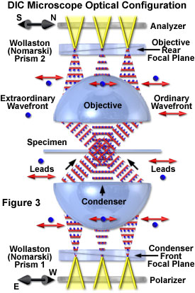
Presented in Figure 3 is an idealized schematic diagram of the major components and light pathways through a typical DIC microscope optical train. Coherent wavefronts emitted from localized regions of the lamp filament pass through the polarizer to form linearly polarized light oriented parallel to the axis indicated by the double arrow adjacent to the polarizing element (45 degrees with respect to the plane of the page). The polarized wavefronts converge on the condenser front focal plane where a Wollaston combination prism is located.
After being sheared by the prism (discussed below), the resulting orthogonal or mutually perpendicular wavefronts are illustrated as a series of red double arrows (wavefront parallel to the page) and blue dots (wavefronts perpendicular to the page). Once they have traversed optical path gradients in the specimen, the wavefronts are gathered by the objective and converge at the rear focal plane, where a second Wollaston prism is positioned. The recombined wavefronts then pass through a second polarizer (the analyzer), which is oriented with a transmission axis indicated by the black double arrow to the left of the polarizing element (90 degrees with respect to the sub-condenser polarizer). Note that the condenser prism is imaged onto the objective prism in Figure 3, so that wavefront shear is matched at every point along the surface of the prisms (which are inverted with respect to one another). Translating either prism along the shear axis (perpendicular to the microscope optical axis and parallel to the page, as discussed below) produces a wavefront mismatch that is uniform across the microscope aperture.
Wollaston and Nomarski Prisms
Birefringent Wollaston and/or Nomarski prisms are inserted in the optical pathway with their shear axis oriented at a 45-degree angle (northwest to southeast) to the polarizer and analyzer. The prisms are composed of two precisely ground and polished wedge-shaped slabs produced from high-grade optical quartz, a uniaxial birefringent crystal. Two quartz wedges having perpendicular orientations of the optical axis must be fabricated to produce a single Wollaston (or Nomarski) prism. The wedges are cemented together at the hypotenuse to generate an optically anisotropic compound plate where the crystallographic optical axis of the first wedge is perpendicular to the optical axis of the second wedge. Incident linearly-polarized wavefronts that enter a prism (oriented with the optical axis at a 45-degree angle to the polarized light) in the condenser aperture are divided into two separate orthogonal waves, termed the ordinary and extraordinary wave.
The mutually perpendicular extraordinary and ordinary component wavefronts are coherent, have identical amplitudes (70.7 percent of the original polarized wave), and travel in the same direction through the lower half of the Wollaston prism. However, the waves propagate at different velocities, which are defined by the dielectric properties along the slow and fast axes of the lower birefringent quartz crystalline wedge. The ordinary wave proceeds through the prism along the fast axis (having a lower refractive index), while the extraordinary ray travels through the slower axis, which has a higher refractive index. In quartz, the refractive index difference between the fast and slow axes is approximately 0.6 percent, and the fast axis is oriented perpendicular to the crystallographic axis of the wedge. Therefore, the ordinary wave traverses a quartz wedge section perpendicular to the optical axis, while the extraordinary wave is oriented parallel to this axis.
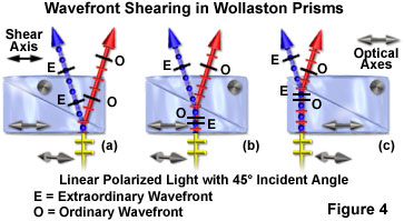
An angular splitting or shear of the wavefronts occurs at the refractive index junction between the cemented quartz wedges, and the waves become spatially separated by an angle defined as the shear angle. At this boundary, the ordinary and extraordinary waves also exchange identities (Figure 4). One wavefront (the ordinary) propagates from a medium of low refractive index into a second medium (the upper wedge) of higher refractive index and is bent toward the normal (perpendicular to the wedge optical axis) according to Snell's law. The second wavefront (the extraordinary) leaves a medium of high refractive index and enters a second medium of lower refractive index, bending the wavefront away from the normal, but at the same angle as the first wavefront.
The shear angle and separation distance is constant for all incident wavefronts across the face of the prism, regardless of the entry point. The direction of wavefront shear is defined by the prism shear axis, which lies in the plane of the Wollaston prism and is parallel to the optical (crystallographic) axis of the lower quartz wedge section (as illustrated in Figure 4). As a result, one of the polarized wavefronts entering a Wollaston prism will be oriented parallel to the direction of the shear axis, while the other is oriented perpendicular to this axis. The shear angle is determined by the design of the prism components (quartz wedge angles, which are less than a degree of arc) and cannot be adjusted in the microscope. However, the shear distance is so minute (usually less than a micrometer) that no observable beam separation occurs in light emerging from the prism.
During their journey through the lower quartz wedge in a Wollaston prism, the ordinary and extraordinary wavefronts experience different refractive indexes, as discussed above. As a result, the ordinary wavefront propagates through the crystal at a higher velocity than does the extraordinary wavefront. When the wavefronts exchange identities at the interface between the lower and upper quartz wedge, the ordinary wavefront becomes the extraordinary wavefront, and vice versa. In addition, the wavefronts undergo a phase shift in the lower half of the prism (due to refractive index differences) that is exactly compensated in the upper half when the geometric paths through the lower and upper half of the Wollaston prism are identical (Figure 4(b)). Wavefronts traversing the prism away from the center experience a longer journey through either the lower prism wedge before being sheared (Figure 4(c)), or the upper wedge after being sheared (Figure 4(a)), before exiting. The extended distance traveled through a single prism wedge by the wavefronts ultimately enables one of the waves (either the ordinary (Figure 4(a)) or extraordinary (Figure 4(c)) to arrive at the quartz-air interface ahead of the other. Across the face of the prism, a constant phase shift per unit length occurs in the direction of shear that is equal, but opposite, for the ordinary and extraordinary wavefronts (Figure 4(a) and 4(c)). At one end of the prism, the extraordinary wavefront emerges ahead of the ordinary wavefront, while at the corresponding position on the other end, the ordinary wavefront exits the prism before the extraordinary wavefront.
If the wavefront incident on a Wollaston prism is polarized in an orientation parallel to the shear axis, then orthogonal splitting of the wavefront will not occur and plane-polarized light will emerge from the prism. Likewise, if the incident polarized wavefront is oriented perpendicular to the prism shear axis, it too will emerge from the prism unchanged with respect to orientation. The ideal situation (and necessary for differential interference contrast microscopy) occurs when the incident polarized wavefront is oriented at a 45-degree angle to the shear axis of the prism. The electric vector of linearly polarized light entering from this angle is bisected into two component vectors, each vibrating in the plane of the fast or slow axis of the quartz crystal and having the root-mean-square (70.7 percent) amplitude of the original wavefront. Both Wollaston and Nomarski prisms exhibit orientation-dependent properties. A collimated linearly polarized light beam entering the opposite side of the prism (this time from the top) at a 45-degree angle will also produce orthogonal extraordinary and ordinary wavefronts. However, the polarization of the waves will be reversed.
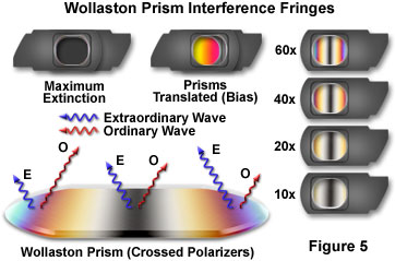
When a Wollaston or Nomarski prism is sandwiched between two crossed polarizers and examined with light transmitted through both polarizers and the prism, a pattern of parallel interference fringes with a predominant central black band (fringe) can be observed (illustrated in Figure 5). These patterns result from interference between the obliquely pitched ordinary and extraordinary wavefronts emerging across the face of the prism. To the left and right of the central dark interference fringe, the peripheral fringes display increasing orders of the classical polarization interference color spectrum. Prism wedges designed for objectives having different focal lengths and numerical apertures are cut at increasingly shallow angles (as magnification and numerical aperture increase) to yield narrower interference fringe banding. This concept is illustrated on the right-hand side of Figure 5 for a series of fixed Nomarski prisms designed for successively higher objective magnifications (indicated in the figure).
If a first-order compensator (red plate) is added to the crossed polarizer sandwich in a diagonal position (not illustrated in Figure 5), the black fringe is replaced with interference colors showing subtraction (yellow) on one side and addition (blue) on the other side of the original dark fringe position. Adding a second Wollaston or Nomarski prism on top of the first will compensate the phase shifts (and resulting interference fringes) of the first prism across the entire length, resulting in extinction (illustrated in Figure 5; note that this effect can only be observed if the two prisms employed for the experiment have the same shear angle). By translating one of the prisms laterally with respect to the other, a uniform bias, or change in path length, will be introduced and can be observed through the sandwich (Figure 5). Sliding the prism in one direction will darken and then lighten the prisms, while sliding it in the other direction will produce a series of uniform interference colors (starting with first-order yellow).
Interference fringes observed in a Nomarski prism sandwiched between two polarizers appear to float in space a few millimeters above the prism. However, when the same fringes are viewed using a Wollaston prism, they appear to lie inside the prism. The location of the interference fringes for either a Nomarski and Wollaston prism is termed the interference plane. Because the interference plane in a conventional Wollaston prism is positioned in the central portion of the prism, at approximately the centerline between the wedges (Figure 6), it is difficult to adapt a Wollaston prism for use with standard microscope objectives. This problem arises because the interference plane of the prism must coincide and overlap with the rear focal plane (also termed the diffraction plane) of the objective, which often lies below the thread mount inside a glass lens element.
Most manufacturers circumvent the objective aperture clearance problem by employing Nomarski (occasionally termed modified Wollaston) prisms both for beam shearing and recombination duty in the condenser and objective focal planes, respectively. Due to a specialized design, as discussed below, Nomarski prisms have an interference plane that is displaced to a site several millimeters outside the prism, rather than spanning the wedge elements as in the traditional Wollaston design. Nomarski prisms do not require being physically located in the objective or condenser focal plane, but can be positioned some distance away. Although Nomarski prisms do not produce better contrast, they avoid the potential problem of interference fringes becoming visible in the viewfield. It should be noted that Leica Microsystems once produced a popular microscope known as the Smith T differential interference contrast system, which incorporated standard Wollaston prisms into specially designed objectives. However, this design strategy is the rare exception, rather than the rule.
The Nomarski prism, like a Wollaston prism, consists of two optical quartz wedges cemented together at the hypotenuse. One of the wedges is identical to a conventional Wollaston quartz wedge and has the optical axis oriented parallel to the surface of the prism. However, the second wedge is modified by cutting the quartz crystal in such a manner that the optical axis is oriented obliquely with respect to the flat surface of the prism. When the wedges are combined to form a birefringent compound prism, the focal plane (and interference fringes produced when polarized light passes through the prism) lies outside the prism plate, as described above and illustrated in Figure 6. This effect occurs because shear now takes place at the air-quartz interface of the lower wedge, and refraction at the interface between the quartz wedges causes the sheared wavefronts to converge with a crossover point outside the prism. The actual position of the Nomarski prism focal plane can be adjusted over a range of several millimeters by altering the oblique angle of the optical axis in the second quartz wedge utilized to construct the prism.
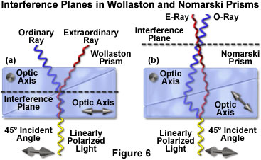
Although Nomarski prisms are widely employed as objective prisms in modern differential interference contrast microscopes, there are fewer spatial constraints for condenser prisms, which can often be positioned precisely within the aperture plane. Therefore, a conventional Wollaston prism can sometimes be inserted into the microscope condenser, but in many cases, a Nomarski prism is used instead. When a Nomarski prism is utilized in the condenser, the prism is designed to produce an interference plane that is located much closer to the prism than those constructed for use with objectives. As a result, aside from being mounted in frames having different geometries, the two Nomarski prisms found in modern DIC microscopes are cut differently and are not interchangeable. In summary, for differential interference contrast microscopy, the condenser prism (also referred to as a secondary, auxiliary, or compensating compound prism) acts as a primary beamsplitter to shear the polarized wavefront, while the objective prism (the principal prism) recombines the separated waves and regulates the degree of retardation between the ordinary and extraordinary wavefronts.
It is important to remember that aligning the microscope for Köhler illumination is a critical and requisite step to ensure correct positioning of the Nomarski prism interference planes for coincidence with the conjugate aperture planes of the condenser and objective. The central, or zeroth-order interference fringe, which is observed when a Nomarski prism is placed between crossed polarizers (as described above), can be used to determine the correct orientation of the prisms during alignment of the microscope.
DIC Wavefront Relationships and Image Formation
After emerging from the condenser Wollaston or Nomarski prism at the aperture plane, the sheared ordinary and extraordinary coherent wavefronts are focused by the lens elements of the condenser and travel through the specimen before being collected by the objective. Along their trajectories between the condenser and objective, the wavefronts remain parallel to one another and are separated by a shear distance derived from the geometrical constraints of the condenser prism. The spatial separation between wavefronts (shear distance) varies with condenser and objective numerical aperture, but has practical limits between 0.1 and 1.5 micrometers, a linear range that is designed to be slightly smaller than (or in some cases equal to) the lateral resolution of the objective. Resolution in differential interference contrast can be increased (at the expense of contrast) by reducing the shear distance to about one-half the maximum resolution of the objective.
Most microscope manufacturers compromise on the shear distance versus resolution (and contrast) trade-off, and produce prisms that have a maximum shear distance of about 0.6 micrometers for lower magnification objectives (10x) down to a minimum approaching 0.15 micrometers for the higher magnification objectives (60x and 100x). Regardless of the shear distance, however, it is important to note that closely spaced wavefront pairs, spatially distributed across the entire microscope aperture, sample every point in the specimen to ultimately provide dual-beam interference at the image plane.
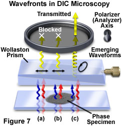
When undisturbed by the presence of a specimen, the coherent wavefront pairs experience identical optical path differences between the specimen and image planes and arrive at the objective rear focal plane having the same phase relationship as when they left the condenser. The Nomarski prism located behind the objective recombines the wavefronts in the objective focal plane to generate linearly polarized light having an electric vector vibration orientation identical to that of the substage polarizer transmission axis. Linearly polarized wavefronts exiting the objective prism are blocked by the second polarizer (or analyzer), which has a transmission axis oriented perpendicular to that of the polarizer (Figure 7(a) and 7(b)). As a result, the image background observed in the viewfield appears very dark or black, a condition referred to as extinction.
Without specimen-induced phase shifts, the beamsplitting action of the condenser prism is exactly matched and reversed by the beam-recombining effect of the objective Nomarski prism to ultimately produce linearly-polarized light. In other words, when the microscope is properly configured for Köhler illumination (a critical prerequisite for high-resolution differential interference contrast microscopy), the condenser and objective operate in conjunction to project an image of the light source and condenser prism onto the objective prism. The objective Nomarski prism, which is inverted in orientation with respect to the condenser prism, introduces a phase shift that exactly compensates the linear phase shift between the wavefronts produced by the condenser prism. This action occurs for all paired wavefronts across the entire microscope aperture. The axes of both the condenser and objective prisms are parallel to each other and oriented at a 45-degree angle with respect to the transmission axes of the crossed polarizers (polarizer and analyzer). The orientation axis of the two prisms is termed the shear axis, an important concept that defines the axis of lateral separation between the ordinary and extraordinary wavefronts from the time they leave the condenser prism until they are recombined by the objective prism and arrive at the image plane.
In the event that coherent paired wavefronts encounter a phase gradient present in the specimen while passing from the condenser to the objective, wavefront distortion is induced and the waves will undergo a phase shift along the shear axis and traverse slightly different optical paths (although no change in polarization occurs). Upon arriving at the objective prism, the phase-shifted paired wavefronts are recombined to generate elliptically polarized light (in contrast to the linearly polarized light produced in the absence of a specimen). The electric vector of the resultant wavefront, which is no longer planar, sweeps out an elliptical pathway as it travels through the region between the objective prism and the analyzer (as illustrated in Figure 7(c)). Because a component of the elliptical wavefront is now parallel to the transmission axis of the analyzer, some portion of the wave will pass through analyzer and produce plane-polarized light having a finite amplitude and ultimately being able to generate intensity in the image plane.
In summary, optical path gradients in the specimen induce phase shifts in the coherent paired wavefronts sheared by the condenser prism and passing through on parallel trajectories. These phase shifts are translated into phase differences by the objective Nomarski prism, creating elliptically polarized light that is capable of passing a linear component through the analyzer and creating an image. In fact, over the entire specimen field, the presence or absence of phase gradients creates a combination of linearly and elliptically polarized wavefronts that are selectively passed by the analyzer according to the azimuths of their vibrational planes. The wavefronts that are able to pass through the analyzer are all plane-parallel and can generate an amplitude image of the specimen through interference at the image plane. When the objective prism exactly compensates the effects of the condenser prism (as it does in Köhler illumination), the analyzer blocks wavefronts originating from all spatial locations of the field lacking phase shifts (no specimen phase gradients). The resulting background observed in the viewfield is dark (exhibiting total extinction) with the exception of regions displaying steep specimen refractive index or thickness gradients, which appear much brighter (usually in outline form). The perceived image appears very similar to images generated by the classical, and simple, darkfield illumination technique.
These concepts are depicted graphically in Figure 8, which presents phase relationships between the sheared wavefronts after passing through a phase specimen (having higher refractive index than the surrounding medium), and their corresponding amplitude (or intensity) profile at the image plane. Mutually perpendicular wavefronts (labeled Σ(1) and Σ(2); see Figure 8(a)) passing through the specimen are distorted and display localized regions of phase retardation (termed differential phase retardations). The objective Nomarski prism recombines the wavefronts by canceling the angular wave shear introduced by the condenser prism, generating a lateral displacement of the wavefront deformation in the process. The distorted wavefront profiles (for both the extraordinary and ordinary components) reconstructed in the image plane along the shear axis are illustrated in Figure 8(a) when the dual prism instrument configuration has been adjusted to maximum extinction. Phase retardation (φ) introduced to the wavefronts by the specimen is indicated on the ordinate (measured in nanometers), while the width of the dip along the shear axis (x) represents the magnified specimen diameter (in this case, a single droplet of oil).
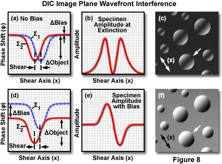
After the phase-retarded wavefronts in Figure 8(a) have been transmitted through the analyzer and are reunited by constructive and destructive interference at the image plane, the resulting intensity distribution can be represented as an amplitude plot along the shear axis (Figure 8(b)). For the symmetrical oil drop specimen considered in this example, the amplitude plot as a function of distance across the shear axis produces a dark central cavity flanked on either side by bright regions (see Figure 8(b)). A digital image of the actual specimen observed in the microscope (Figure 8(c)) reveals spherical microdomains having bright edges superimposed on a black background and a dark interference fringe banding the center. The images presented in Figure 8 were recorded on an upright microscope configured with a DIC optical system. Inverted tissue culture microscopes produce the same basic result, however, the central interference fringes bisecting the hemispherical oil droplets will be oriented perpendicular to those illustrated in Figure 8(c).
Introduction of Bias Retardation
In a differential interference contrast microscope adjusted for maximum extinction, the viewfield is rendered with a dark, almost black, background and exhibits very high sensitivity to specimen regions having both increasing and decreasing phase gradients. As illustrated in Figure 8(c), some specimen detail is obscured or very difficult to resolve in this configuration, and the zeroth-order interference fringe can often be observed traversing highlighted features. In practice, the objective Nomarski prism is offset laterally along the shear axis to uniformly shift the relative phase displacement of the ordinary and extraordinary wavefronts passing through the specimen. Thus, the polarization vector orientation of light emerging from the objective prism can be adjusted from linear through various degrees of elliptical and even to circular. Shifting the phase displacement of the ordinary wavefront with respect to the extraordinary wavefront through translation of the objective prism is often termed introduction of bias retardation in DIC microscopy.
As the objective Nomarski prism is shifted laterally (either to the left or right of the microscope optical axis), wavefront pairs contributing to the background become increasingly retarded and out of phase with respect to one another. As a result, the degree of elliptical polarization is increased in wavefronts entering the analyzer, and the background intensity progressively transitions from black to medium and lighter shades of gray. In addition, the introduction of bias retardation shifts the position of the zeroth-order interference fringe and produces corresponding changes to the intensity levels of phase gradients in the specimen. These result in the generation of orientational-dependent bright highlights and dark shadows superimposed on the now lighter background (having a color often termed zero-order gray). The final DIC image does not rely on the optical path difference being introduced exclusively through translation of the objective prism, and the same result can be obtained when the condenser prism is moved along the microscope optical axis. However, in most instruments it is far more convenient to produce bias retardation by shifting the position of the objective prism rather than prisms housed in a condenser turret.
Intensity gradients introduced to the specimen by altering the bias retardation occur along the shear axis of the condenser and objective prisms, and generally appear to be originating from a 45-degree angle (northwest to southeast or vice versa) when the specimen is observed in the eyepieces (see Figure 8(f)). Note that the gradients illustrated in Figure 8(f) were recorded with an upright microscope. Inverted microscopes produce intensity gradients that are oriented perpendicular to those observed in upright microscopes. Shifting the prism in one direction or another will affect the interference fringe offset and vary the phase relationship (retarded or advanced) between the ordinary and extraordinary wavefronts, thus reversing the shadow-cast orientation in the specimen.
The net result of introducing bias retardation is to render the specimen image in pseudo three-dimensional relief where regions of increasing optical path difference (sloping phase gradients) appear much brighter (or darker), and those exhibiting decreasing path length appear in reverse. Specimen features appear similar to elevated plateaus or sunken depressions depending on the phase gradient orientation, which is a distinguishing feature of differential interference contrast. However, the three-dimensional appearance only corresponds to phase gradients and should not be confused with the actual specimen geometry (as is too often the case). In some situations, real topographical features are also sites of changing phase gradients, but in the absence of information obtained as the result of independent investigations, this fact should not be assumed.
Introduction of bias retardation in differential interference contrast microscopy is illustrated in Figure 8(d) through Figure 8(f) for a phase specimen consisting of several hemispherical oil droplets. When the microscope is adjusted for maximum extinction, the ordinary and extraordinary wavefronts display a phase shift along the shear axis, but do not exhibit a phase difference in regions corresponding to the background (Figure 8(a)). Addition of bias retardation by translation of the objective prism shifts the relative phase of one wavefront with respect to the other (Figure 8(d)), but the wavefront shear remains the same. Upon interference at the image plane, the resulting amplitude (or intensity) plot, as a function of shear distance (Figure 8(e)), displays a bright edge region on one side of the oil droplet and a dark region on the opposite side. When observed in the microscope, the specimen exhibits a shadow-cast appearance as if it were being illuminated from a highly oblique angle (see Figure 8(f)). In order to observe the difference between maximum extinction and addition of bias retardation, compare the specimen images presented in Figure 8(c) and (f). The shadow orientation, which is dependent on the shear axis (double-headed arrows in Figure 8(c) and (f)), can be reversed by translating the objective prism by the same amount in the opposite direction.
Bias has been traditionally introduced into the differential interference contrast microscope by translating the objective Nomarski prism back and forth along the optical axis using a fine adjustment knob located at the end of the mounting frame (usually positioned in the microscope nosepiece housing or an intermediate tube). An alternative technique, which is growing in popularity, is to mount a quarter-wavelength retardation plate in fixed orientation between the polarizer and condenser prism (termed de Sénarmont DIC compensation). At maximum extinction, the fast axis of the retardation plate is aligned with the transmission axis of the polarizer, and both optical units can be (and often are) contained within the same housing on the base of the microscope. An alternative location for the de Sénarmont compensator, in microscopes equipped with the appropriate intermediate tube, is between the objective prism and the analyzer.
In order to introduce bias using the de Sénarmont compensator, the polarizer transmission axis is rotated (up to plus or minus 45 degrees) with respect to the fast axis of the retardation plate, which remains fixed at a 90-degree angle relative to the analyzer transmission axis. When the compensator fast axis coincides (is parallel) with the transmission axis of the polarizer, only linearly polarized light passes through the de Sénarmont compensator to the condenser prism. However, when the polarizer transmission axis is rotated, wavefronts emerging from the quarter-wavelength retardation plate become elliptically polarized. Rotating the polarizer in one direction will produce right-handed elliptically polarized light, while rotating the polarizer in the other direction will alter the vector trajectory to generate a left-handed elliptical sweep.
When the orientation of the polarizer transmission axis reaches either plus or minus 45 degrees (equivalent to one-quarter wavelength retardation), light passing through the compensator becomes circularly polarized (again in either a left-handed or right-handed sense). Because elliptically or circularly polarized light represents a phase difference between the ordinary and extraordinary wavefronts emerging from the de Sénarmont compensator, bias is introduced to the system when the wavefronts enter the condenser prism and become sheared. Positive bias is obtained when the polarizer is rotated in one direction, while negative bias is introduced by rotating the polarizer in the opposite direction.
Regardless of whether bias is introduced into a differential interference contrast system by translating the objective Nomarski prism or by rotating the polarizer on a de Sénarmont compensator, the net result is the same. As previously discussed, in a properly configured microscope that is aligned for Köhler illumination, an image of the light source and condenser prism is transferred by the optical system (condenser and objective) onto the inverted second Nomarski prism located at the objective rear focal plane. The linear phase shift across the face of the condenser prism is precisely compensated by an opposite phase shift in the objective prism. Translation of the objective prism along the shear axis does not alter the phase shift distribution, but instead, adds or subtracts a constant phase difference across the entire microscope aperture. In the same manner, rotating the polarizer in a de Sénarmont compensator also introduces a variable and controlled phase difference. The matched prism system enables image formation to occur with the same bias retardation for every wavefront pair projected from the condenser aperture, irrespective of the route through which it traverses the specimen to reach the objective.
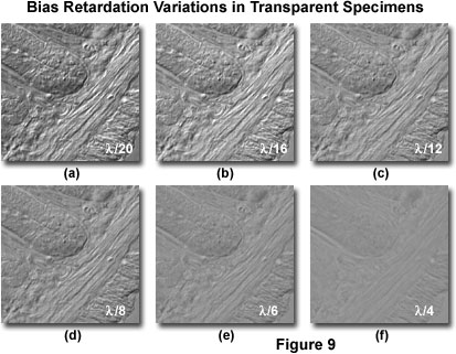
Presented in Figure 9 is a series of digital images recorded in DIC using a bias retardation range of one-twentieth to a quarter wavelength in several intermediate steps. The specimen is a 15-micrometer section of fixed and mounted murine intestine that contains regions of fluctuating thickness. Rendition of specimen detail and the shadow-cast pseudo three-dimensional effects are the most pronounced at the lower bias retardation values (Figure 9(a) and 9(b)), but contrast and definition of fine specimen detail both deteriorate as bias retardation is increased (Figure 9(c) through 9(f)). At the highest bias retardation value (one-quarter wavelength; Figure 9(f)), contrast is extremely poor and very few structural details are visible. For this particular specimen, the optimum retardation range appears to lie between one-twentieth and one-twelfth of a wavelength.
As the optical path gradient in a specimen increases, so does image contrast. Altering the bias retardation to varying degrees can also produce significant contrast fluctuations in the specimen as observed in the eyepieces (Figure 9). In general, the optimum degree of displacement between the ordinary and extraordinary wavefronts induced by translation of the objective prism, or by rotating the polarizer in a de Sénarmont compensator, is on the order of less than one-tenth wavelength. However, this value is largely dependent on specimen thickness, and the useful range of bias retardation for biological specimens lies between one-thirtieth and a quarter wavelength. Contrast in specimens having very large optical gradients can often benefit from even greater bias retardation values (up to a full wavelength). The introduction of bias retardation into a differential interference contrast microscope enables phase specimens to be observed with greater ease, and dramatically facilitates imaging efforts with traditional film or digital camera systems.
Compensator Retardation Plates in DIC Microscopy
Bias retardation between the ordinary and extraordinary wavefronts in differential interference contrast can also be manipulated through the use of compensators originally targeted as quantitative retardation measuring devices and contrast-enhancing elements for polarized light microscopy. Compensating plates bestow greater control for adjusting the contrast of specimen details in relation to the background intensity and color values, and also enable more precise tuning of the bias value between wavefronts. These birefringent components are also frequently employed for optical staining of transparent specimens, which are normally rendered over a limited range of grayscale values.
When a standard objective Nomarski prism is translated along the microscope optical axis beyond path differences of one-quarter wavelength, both specimen features and the background acquire a spectrum of Newtonian interference colors similar to those observed in polarized light microscopy. The specimen and background become optically stained with a transition of color that migrates through a series of gray values through white, yellow, red-blue and higher orders. Optical staining produces dramatic and beautifully colored images, but has limited use for scientific applications. Usually, the optimum specimen contrast is limited to the range of one-twentieth to one-quarter wavelength of retardation.
Compensators can be inserted into the optical pathway of a DIC microscope between either the objective prism and the analyzer or the polarizer and the condenser prism. Many microscopes have a slot located in the intermediate tube or substage condenser housing designed for this purpose. Addition of a first-order compensator (often termed a full-wave or first-order red plate) having a retardation value equal to a full wavelength in the green region of visible light (approximately 550 nanometers), introduces a spectrum of interference colors to the specimen and background. With the compensator in place, green light is unable to pass through the analyzer because it emerges from the retardation plate linearly polarized with an electric field vector having the same orientation as the polarizer. However, wavefronts in the red and blue spectral regions experience retardations less than a wavelength and become elliptically polarized, allowing them to pass a component through the analyzer. As a result, these colors become mixed to form a magenta background in the field of view.
Thus, when a specimen is observed in white light with differential interference contrast optics and a first-order compensator, the background appears magenta while image contrast is displayed in the second-order blue and first-order yellow colors (depending on orientation) of the Newtonian interference color spectrum. With the compensator in place, small variations in bias retardation obtained by translation of the Nomarski prism (or rotating the polarizer in a de Sénarmont compensator) yield rapid changes to interference colors observed in structures having large optical phase gradients. This technique is useful for introducing color (optical staining) to regions having high refractive index boundaries, such as cellular membranes, large intracellular particles, cilia, and the nucleus. The interference colors displayed by specimen features can be compared to the values on a Michel-Levy color chart to obtain an estimate of the optical path difference.
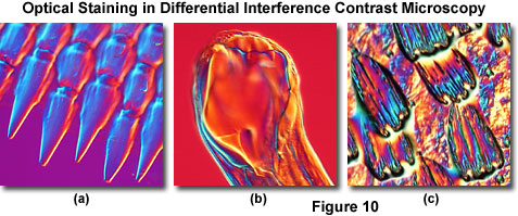
Illustrated in Figure 10 are several transparent specimens that have been optically stained and rendered in pseudo three-dimensional relief through DIC optical techniques. Figure 10(a) depicts projections at the edge of a ctenoid fish scale, while the mouth of a canine hookworm (Ancylostoma caninum) is featured in Figure 10(b). Colorful wing scales of the Great Leopard moth (Ecpantheria scribonia) are presented in Figure 10(c). In all cases, the Nomarski prism was translated across the microscope optical axis to a bias retardation value exceeding a full wavelength. Although these images do not reveal hidden scientific information pertaining to the specimens, they do have the potential to advance the technique of DIC optical microscopy as a legitimate bridge between science and art.
On microscopes equipped with a de Sénarmont compensator for introducing bias into a differential interference contrast optical system, a full-wave retardation plate can be added to optically stain the specimen with Newtonian interference colors and provide more quantitative information about path differences. As discussed above, the de Sénarmont compensator is frequently employed in DIC microscopy to obtain precisely measured levels of bias retardation, but the device is also useful to monitor alignment of the optical components. In video-enhanced DIC microscopy, de Sénarmont compensators are often utilized to optimize contrast in specimen detail that lies below the resolution limit of the microscope.
Interpretation of DIC Images
Among the most notable and well-recognized aspects of images obtained with differential interference contrast microscopy is the high degree of visible relief, manifested through a shadow-cast effect that bestows a pseudo three-dimensional realism. In general, specimens appear as through they were illuminated from a low angle with a highly oblique light source, reminiscent of the results obtained with traditional oblique illumination or Hoffman modulation contrast. In caution, however, images should always be interpreted with the understanding that shadows and highlights in the shadow-cast renditions only indicate the sign and slope orientation of phase or optical path gradients and do not necessarily reveal accurate geometrical or topographical parameters.
From observing the shadow-cast orientation present in almost every image produced through bias retardation, the direction of optical shear is obvious and can be precisely defined as the axis connecting regions displaying the highest and lowest intensity values. Another consideration that should be taken into account is the relationship between the specimen and its surrounding medium, because shadow directions are often reversed for specimen details that possess either a higher or lower refractive index than their surroundings. As a result, dense subcellular particles, such as nuclei, nucleoli, mitochondria, filaments, metaphase chromosomes, and lysosomes usually display the appearance of raised elevations (hilltops), while lower refractive index inclusions (for example, pinocytotic vesicles, aqueous vacuoles, and lipid droplets) appear to be sunken depressions (craters).
The level of contrast bestowed on specimen phase gradients (and the degree of pseudo three-dimensionality) by differential interference contrast is a function of the amount of bias retardation introduced into the optical system by translating the Nomarski prism or rotating the polarizer in a de Sénarmont compensator. Because the shear axis is fixed by Nomarski and Wollaston prism design and other constrains involved in wavefront orientation for differential interference contrast, the axis direction cannot be altered to affect specimen contrast through a simple setting on the microscope. However, the relative phase retardation between ordinary and extraordinary wavefronts can be reversed by relocating the objective prism from one side of the microscope optical axis to the other (shifting the bias retardation from negative to positive, or vice versa). This operation can also be accomplished by rotating the polarizer to the corresponding negative value on a de Sénarmont compensator. When the phase retardation is altered as just described, the orientation of bright and dark edges on the specimen is reversed by 180 degrees. In essence, the only mechanism available to the microscopist to change the shear axis relative to the specimen is to reorient the specimen itself, a maneuver that benefits from the utilization of circular 360-degree rotatable stages (designed primarily for polarized light microscopy).
In differential interference contrast images, shadow and highlight intensity is greatest along the shear axis of the microscope, and regions of constant refractive index display intensity values that are identical to that of the background. When a specimen having spherical geometry (Figure 8(f)) is examined from several azimuths for contrast at the edges bordering the background, it is discovered that contrast is minimal in the regions perpendicular to the shear axis. In fact, contrast differences between the specimen and background gradually decrease until they reach a minimum value in the direction defining the axis of the zeroth-order interference fringe (perpendicular to the shear axis). In Figures 8(c) and 8(f), the specimen regions exhibiting the lowest level of contrast (indicated by an unlabeled white arrow) are the edges in the central area of the oil droplets lying exactly perpendicular to the shear axis. In order to verify this concept, compare an edge where the interference fringe meets the background in the image recorded at maximum extinction (Figure 8(c)) to the corresponding region in the image generated after introduction of bias retardation (Figure 8(f)). In the areas marked by the unlabeled white arrow, the ordinary and extraordinary wavefront distortions have aligned profiles, which are subtracted at the analyzer to cancel residual retardation and yield an intensity value that exactly matches the background.
Each specimen examined in differential interference contrast microscopy will have an optimum bias retardation setting that generates a maximum level of contrast in the final image. Very thin specimens that display a shallow refractive index gradient, such as living cells in culture, generally benefit from equally low bias settings only slightly larger than the largest phase shift present in the specimen (on the order of approximately one-twentieth of a wavelength, or approximately 30 nanometers). However, thicker specimens often require higher bias settings (up to one-quarter wavelength) at large condenser apertures to produce satisfactory results, usually through optical sectioning. Because many specimens are composed of features displaying a variety of different sizes and refractive indices, the optimum bias retardation setting is usually a compromise.
Azimuthal effects of orientation phenomena in differential interference contrast for several specimens are presented in Figure 11. In all cases, the shear axis is directed northwest to southeast, but is not indicated on the individual digital images. Figure 11(a) and 11(b) illustrate the periodic spacing of pores and striae exhibited by a mounted frustule from the diatom Gyrosigma attenuatum. When the long axis of the frustule is oriented perpendicular to the shear axis (Figure 11(a)), the pores appear to merge into a series of closely spaced ridges and are not resolved individually. In contrast, reorientation of the frustule in a direction parallel to the shear axis reveals the knob-like geometry of pore structure in this species.
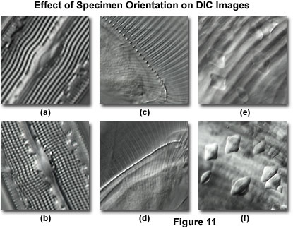
The thorax region containing gill ribs of a fresh water Daphnia (water flea) is presented in Figure 11(c). In this orientation, individual rib structures are clearly visible (perpendicular to the shear axis) and joined to a common spine, which appears as a long series of knobs parallel to the shear axis. When the specimen is rotated 90-degrees (Figure 11(d)), much of the rib structure loses contrast, and the spinal knobs merge into a single ridge. Finally, inclusions in a ctenoid fish scale lack contrast and are difficult to distinguish when superimposed over the striated body spines (Figure 11(e)). Rotating the specimen to bring the spines parallel to the shear axis (Figure 11(f)) reduces their contrast and renders the inclusions clearly visible.
A number of factors should be considered when adjusting bias retardation to produce optimum specimen contrast. The level of bias that must be introduced to maximally darken one slope or edge of the specimen also yields the maximum possible contrast between the specimen and the background. Therefore, for each specimen, one particular objective prism (or de Sénarmont compensator) setting will usually introduce the greatest degree of contrast. When this value is exceeded, contrast will decrease. Thicker specimens, which often suffer from light scattering artifacts, usually require a larger bias retardation setting (up to a full wavelength) than thinner specimens to obtain extinction in regions having significant phase gradients. Finally, when the iris diaphragm opening size in the condenser exceeds 75 percent of the objective rear aperture, contrast is reduced as a result of excessive light scattering in the optical system. With this difficulty in mind, use caution when opening the condenser aperture to perform optical sectioning experiments.
Optical Sectioning
The ability to image a specimen in differential interference contrast with large condenser and objective numerical apertures enables the creation of remarkably shallow optical sections from a focused image. Without the disturbance of halos and distracting intensity fluctuations from bright regions in lateral planes removed from the focal point, the technique yields sharp images that are neatly sliced from a complex three-dimensional phase specimen. This property is often utilized to obtain crisp optical sections of cellular outlines in complex tissues with minimal interference from structures above and below the focal plane.
In all traditional forms of transmitted and reflected light microscopy, the condenser aperture iris diaphragm plays a major role in defining image contrast and resolution. Reducing the aperture size increases the depth of field and overall image sharpness while simultaneously producing enhanced contrast. However, if the diaphragm is closed too far, diffraction artifacts become apparent and resolution is sacrificed. Often, the optimum aperture setting is a compromise between accurately rendering specimen detail in sufficient contrast and retaining the resolution necessary to image minute features while avoiding diffraction artifacts.
High-performance differential interference contrast microscope optical systems produce excellent contrast with the condenser iris diaphragm partially closed (approximately 70 percent of the objective rear aperture size), but also perform superbly when the diaphragm is opened to match the objective aperture size. In order to achieve the optimum balance between resolution and contrast for optical sectioning, the microscope must be properly configured for Köhler illumination and the prism components and polarizers should be accurately aligned. High numerical aperture objectives designed for oil immersion should only be utilized to image specimen slides that have the underside oiled to the condenser.
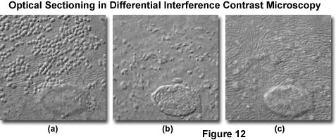
At high magnifications and numerical apertures (for example, 100x and 1.4), the depth of field in differential interference contrast approaches a limiting value of about 400 nanometers (0.40 micrometers; about 1.5 times the lateral resolution limit of the objective). Optical sections taken through the central region of a human buccal epithelial cell at high magnification (100x objective) and numerical aperture (1.30) are illustrated in Figure 12. The cell is approximately 3 micrometers thick near the nucleus, and depth of field for the configuration utilized to obtain the images in Figure 12 was approximately 0.5 micrometers. Bacteria are clearly visible on the upper surface of the cell (Figure 12(a)), as are parallel, swirling ridges in the membrane that closely resemble the texture of human fingerprints. A bulge in the membrane corresponding to the nucleus is also visible in the lower central portion of the figure. As the focal plane is shifted to the interior of the cell (Figure 12(b)), details of the nuclear structure and intracellular particles become visible. Finally, at the lower boundary where the cellular membrane rests on the surface of the microscope slide (Figure 12(c)), numerous folded ridges are revealed (similar to those observed on the upper surface).
When performing optical sectioning experiments with thicker biological specimens (especially those immersed in aqueous saline solutions), the microscopist must be alert to the possible introduction of spherical aberration produced by refractive index discontinuities at the interface between the coverslip and mounting medium. These artifacts will reduce resolution at higher penetration depths in the optical section series.
A significant amount of the current research and development of theory in differential interference contrast is focused on the striking optical sectioning characteristics of the technique. Ultimately, a quantitative estimate of the three-dimensional refractive index profile from a specimen may be achieved through computational models. In addition, current research is also directed at new models being developed for the DIC optical components and image formation in partially coherent transmitted light.
Conclusions
Differential interference contrast microscopy is basically a beam-shearing interference system in which the reference beam is sheared by a minuscule amount, generally somewhat less than the diameter of an Airy disk. In fact, each point in the specimen is represented by two overlapping Airy disks in the final image, one being brighter and the other darker than the background. The basic microscope system, first devised by Francis Smith 1955, is a modified polarized light microscope with two Wollaston prisms added, one to the front focal plane of the condenser and the second at the rear focal plane of the objective.
Later modifications, suggested by Georges Nomarski, enabled the prisms to be physically located away from the optical aperture conjugate planes. The condenser prism converts each wavefront illuminating the specimen into two slightly displaced, parallel beams that are orthogonally polarized relative to each other, while the objective prism serves to recombine the beams. The combination of these two prisms, which are mirrored onto one another by the optical system, is a key feature in the ability of differential interference contrast to form sharp images at high numerical aperture.
A phase difference is introduced into the two orthogonal wavefronts by a gradient in the geometric path length or refractive index of the specimen, which results in elliptical polarization for the recombined beam that exits the objective Wollaston prism. Bias retardation can be introduced to the system by translating the objective prism along the microscope optical axis or by combining a quarter-wavelength plate with the polarizer or analyzer. Thus, optimum contrast, field brightness, and sensitivity can be gained by simple rotation of a control knob.
The resulting DIC images possess a shadow-cast appearance that effectively display the gradient of optical paths for both low and high spatial frequencies. Those specimen regions where optical paths increase along a reference direction appear brighter (or darker), while the regions where path differences decrease appear in reverse contrast. Steeper gradients in optical path difference result in greater contrast. A wide variety of specimens are good candidates for imaging with differential interference contrast, including very thin filaments or sharp interfaces, which produce good contrast even when their diameter falls below the resolution limit of the optical system.
Among the chief imaging advantages of differential interference contrast microscopy is that, unlike darkfield or phase contrast, the image of smaller specimen features is not obscured by adjoining regions having large optical gradients. In addition, the shadow-cast appearance of the image on a neutral gray background, coupled to the sensitivity for imaging very small features together with those much larger (for example, minutes appendages to living cells or dynamic inclusions and moving organelles inside a cell), is a significant improvement over traditional phase contrast techniques. These benefits, in addition to the wide dynamic range of contrast control and shallow depth of field, have all contributed to the widespread popularity of the technique.
Contrast in DIC microscopy is directional, exhibiting a maximum along the axis of shear and a minimum in the orthogonal direction. The direction of Airy disk separation (averaging a peak-to-peak separation of one-half to two-thirds the disk radius) coincides with the shear axis of the microscope, which is the direction of maximum contrast. As a result, the DIC contrast transfer function (CTF) is also directional along the shear axis. The lateral displacement between two wavefronts passing through the specimen is approximately half the resolution limit of the objective. This small degree of shear, induced by the Wollaston or Nomarski prism, is similar in action to a high pass filter for the contrast of spatial frequency detail in the specimen. The corresponding modulation transfer function (MTF) closely follows that observed in brightfield illumination for high spatial frequencies, but displays a steep decline for specimen features exceeding several micrometers in size (lower spatial frequencies).
Specimens suitable for observation in DIC include fluid smears, living cell cultures, blood cells, subcellular organelles, unstained tissues, chromosomes, protozoa, embryos, diatoms, polymers, replicas, and relatively thick or ultra thin microtome sections. Additional information can be obtained by examining amplitude and mixed phase-amplitude specimens, such as naturally pigmented protists, algae, and lightly stained histological specimens. The technique is often employed in combination with fluorescence microscopy to reveal the cellular morphology associated with fluorescent regions. When coupled to enhanced video techniques (termed VEC-DIC for video-enhanced contrast differential interference contrast), DIC can be utilized to produce images of structures having dimensions below the optical resolution of the microscope.
