Reflected Darkfield Illumination
One of the most effective ways to improve contrast in the reflected light microscope is to utilize darkfield illumination. In reflected darkfield microscopy, an opaque occluding disk is placed in the path of the light traveling through the vertical illuminator so that only the peripheral rays of light reach the deflecting mirror. These rays are reflected by the mirror and pass through a hollow collar surrounding the objective to illuminate the specimen at highly oblique angles.

A typical reflected light microscope with a cut-away drawing of the vertical illuminator is illustrated in Figure 1. The illuminator is horizontally oriented, 90 degrees to the optical axis of the microscope and parallel to the table top, with the lamp housing attached to the back of the illuminator. Coarse and fine adjustment knobs raise or lower the stage in large or small increments respectively to bring the specimen into sharp focus. The specimen's top surface is upright on the stage facing the objective, which has been rotated into the microscope's optical axis.
Many modern reflected light illuminators are described as "universal" illuminators because, with several additional accessories and little or no dismantling, the microscopist can easily switch from one mode of reflected light to another. It is even possible to slide the reflectors out of the path altogether in order to perform transmitted light observation. Such universal illuminators may include a partially reflecting plane glass surface (sometimes referred to as a half-mirror) for brightfield, and/or a fully silvered reflecting surface with an elliptical, centrally located clear opening for darkfield observation.
Each of these reflecting devices (housed in mirror blocks or cubes) is tilted at a 45 degree angle facing the light traveling along the vertical illuminator and, simultaneously, at a 45 degree angle to the optical axis of the microscope. Both of the respective mirrors direct the light downward at 90 degrees toward the specimen and also permit the upward-traveling reflected light to pass through to the viewing tubes and eyepieces for observation. The best-designed vertical illuminators include condensing lenses to gather and control the light, an aperture iris diaphragm and a pre-focused, centerable field iris diaphragm to permit the desirable Köhler illumination. Affixed to the back end of the vertical illuminator is a lamphouse containing the light bulb, usually a high-performance tungsten-halogen lamp. For very faint darkfield samples, the lamphouse can be replaced with one containing a mercury burner. The burner lamp may be powered by the electronics built into the microscope stand, or (in simpler models) by means of an external transformer.
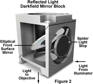
Within the vertical illuminator, light emitted by a 50 or 100-watt low voltage-high intensity tungsten-halogen lamp passes through a collector lens and then through the aperture and field diaphragms before striking the opaque stop in the opening port of the darkfield mirror block located above the objective at the front of the illuminator. The opaque stop blocks the central portion of the light beam allowing only a hollow cylinder of light to pass into the mirror block, as illustrated in Figure 2 below. The field and aperture diaphragms are opened to their maximum positions to avoid blocking peripheral rays of light from the source.
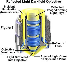
Light entering the mirror block is reflected by a special mirror positioned within a tube inside the block. This mirror is oriented at a 45-degree angle to the incident beam and has an elliptically shaped opening surrounded by a fully silvered front surface mirror. Peripheral rays of light reflected from the elliptical mirror are deflected downward, exiting at the bottom of the vertical illuminator. The cylinder of light then travels through the nosepiece before passing into specially constructed objectives known as Neo, BF/DF, or BD objectives (Figure 3), depending upon the designation of the manufacturer. These objectives are typically designed with optical corrections necessary for use on specimens lacking a coverslip.

Light from the darkfield mirror block travels down the 360-degree hollow chamber surrounding the centrally located lens elements of the specially constructed BD reflected light objectives, as illustrated in Figure 3. This light is directed at the specimen from every azimuth in oblique rays to form a hollow cone of illumination by means of circular mirrors or prisms located at the bottom of the objective's hollow chamber. In this manner, the objective serves as two separate optical systems coupled coaxially such that the outer system functions as a darkfield "condenser" and the inner system as a typical objective.
Darkfield Reflected Light Objectives

Explore how light diffracted, refracted, and reflected from the surface of a specimen enters the front lens of a darkfield reflected light objective.
Start Tutorial »Today, most darkfield reflected light microscope objectives are infinity-corrected and are available in a broad spectrum of magnifications ranging from 5x to 200x. These objectives are also manufactured in various qualities of chromatic and spherical correction, from simple achromats to planachromats and planapochromats. Most, but not all, are designed to be used "dry" with air in the space between the objective and the specimen. Some reflected light objectives are designed to focus at a longer working distance from the specimen than is usual. Such objectives are labeled on the barrel of the objective as LWD (Long Working Distance), ULWD (Ultra-Long Working Distance), and ELWD (Extra-Long Working Distance).
Objective design varies depending upon the manufacturer, but the condenser portion may have one of three classical designs. Catoptric reflecting objectives have a single glass lens element positioned at the nose of the objective and rely on reflections from the internal surface of the barrel to focus light onto the specimen. Another important objective design is the dioptric configuration in which a series of prisms are strategically placed in the hollow outer chamber and used to aim and focus light toward the specimen.
The objective illustrated in Figure 3 is a catadioptric system, which uses both reflecting and refracting optical elements and surfaces to form the oblique hollow cone of illumination necessary to view the specimen in darkfield mode. A cylinder of light entering the hollow periphery of the objective first encounters a curved lens element that directs light to a mirrored internal surface of the objective lens barrel. Light is reflected from the barrel directly through the glass element and is then reflected from the mirrored internal surface of the outer objective barrel, before being refracted to form the hollow cone of illumination by a second lens element. Light diffracted and refracted by the specimen is then able to enter the front lens of the objective. This concept can be further studied by examining the interactive Java tutorial on reflected darkfield objectives.

The necessity of a hollow collar surrounding the lens elements in reflected light objectives requires that the diameter of the objective be significantly greater than that of ordinary brightfield objectives. In most cases, a nosepiece-mounting thread diameter larger than the Royal Microscopical Society (RMS) standard is used in reflected light objectives. This requires that reflected light darkfield objectives have a nosepiece with a larger thread size, which is typically referred to as a BD or BF/DF thread size. Most manufacturers offer objective adapters that convert standard RMS thread size nosepieces to BD thread size, allowing the use of these objectives on reflected light microscopes. Care should be taken to ensure that objectives used on BD thread nosepieces will conform to the tube length of the microscope.
Table 1 lists specifications of a typical series of infinity-corrected Neo planachromat brightfield/darkfield objectives designed for use in reflected light microscopy. Numerical aperture values reach a limit of about 0.90 in this series, which is the practical limitation for "dry" objectives of this design.
Neo D Planachromat Objectives (Infinity-Corrected)
| Magnification | Numerical Aperture |
Working Distance (millimeters) |
|---|---|---|
| 5X | 0.10 | 11.20 |
| 10x | 0.25 | 6.00 |
| 20X | 0.40 | 1.00 |
| 50x | 0.75 | 0.34 |
| 80X (dry) | 0.90 | 0.18 |
| 100x (dry) | 0.90 | 0.30 |
| 150X (dry) | 0.90 | 0.27 |
Table 1
In many modern microscope stands, the Neo type objectives, with appropriate modules or accessories, can be used for darkfield, brightfield, polarized light, Nomarski differential interference contrast (DIC), and reflected light fluorescence observations.
Specimen geometrical constraints often require specialized objectives to properly image all areas of the specimen. Table 2 contains specifications for reflected light darkfield objectives designed to be used at long working distances, and also apochromat objectives that yield superior photomicrographs of specimens at very high magnifications.
Long Working Distance
and Apochromat Darkfield Objectives
(Infinity-Corrected)
| Magnification | Numerical Aperture |
Working Distance (millimeters) |
|---|---|---|
| 20X (ELWD) | 0.40 | 11.0 |
| 50x (ELWD) | 0.55 | 8.2 |
| 100X (ELWD) | 0.80 | 2.0 |
| 100x (Apo) | 0.90 | 0.40 |
| 150x (Apo) | 0.90 | 0.29 |
| 200x (Apo) | 0.90 | 0.30 |
Table 2
Without a specimen on the stage, the field of view in a darkfield reflected light microscope appears black because the oblique rays fall outside the acceptance angle and miss re-entering the objective. When a specimen is placed on the stage, the features of the specimen, including surface irregularities such as grain boundaries, ridges, scratches, depressions or particles, etc., now shine brightly against a black background. The contrast is enormously increased with the result that surface features of the sample, otherwise almost invisible in brightfield, are readily discernible. In fact, many metallurgical and related samples do not require etching or other preparatory procedures in order to produce excellent darkfield images. Color rendition is also spectacular using this method of illumination. The light scattered by specimen detail, which is often obscured in brightfield illumination, is able to enter the objective under darkfield illumination and pass through the central lens elements of the objective eventually to reach the eye or camera.

The photomicrographs illustrated in Figure 4 represent a comparison of brightfield and darkfield reflected light images of surface features on the MIPS R10000 microprocessor integrated circuit using BD-type objectives. Bonding wires at the edge of the chip die are very evident in the photomicrographs. The surface of the computer chip is coated with a Passivation layer of silicon nitride that protects electrical components from exposure to the atmosphere. Light reflected and refracted by this layer is responsible for the apparent color in portions of the photomicrographs.
The brightfield image in Figure 4(a) shows that incident light does not reflect from the bonding wires, which appear very dark in the photomicrograph. Initials of the chip designers, which were incorporated onto the chip's surface during the photolithographic fabrication process, appear in the right central portion of both photomicrographs. These initials, along with the bonding wires, reflect oblique light back into the objective, as illustrated in the darkfield photomicrograph in Figure 4(b). These two methods of illumination can be successfully used to complement one another during inspection of integrated circuit surfaces.

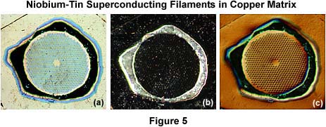
The photomicrographs in Figure 5 serve to further illustrate how different illumination techniques can complement each other when combined with the examination of specimens under darkfield illumination. The specimen is a bundle of niobium-tin superconducting filaments embedded in a copper/bronze matrix that compose a flexible wire used in low-temperature superconducting magnets of high field strength. The photomicrograph in Figure 5(a) was taken under brightfield illumination and illustrates the bundle of filaments surrounded by a very dark area and a blue barrier layer that is composed of tantalum. The dark area in Figure 5(a) is a layer of residual tin that is left over from a heat treatment step in the construction of the wire bundle. Superconducting filaments and the tantalum barrier are not visible Figure 5(b), which is a darkfield photomicrograph of the same area imaged in Figure 5(a). However, the residual tin layer reflects light into the objective and appears as a bright metal band surrounding the filaments. Figure 5(c) is a photomicrograph of the same viewfield in reflected differential interference contrast. The bronze matrix surrounding the individual filament bundles is very evident, but the residual tin and tantalum barrier layers are difficult to discern. This series of photomicrographs serves to demonstrate how the techniques of brightfield, darkfield, and differential interference contrast can be used to complement each other and provide a more thorough investigation of the specimen.
The following section reviews the steps in the configuration and alignment of a microscope for reflected (incident) darkfield illumination.
Reflected (Incident) Darkfield Configuration
- Select a sample that has good reflective properties and place it onto the microscope stage. Using the 10x objective, adjust the microscope for reflected light Köhler illumination. Verify that darkfield (Neo, BF/DF, or BD) objectives are inserted into the nosepiece and are ready for use.
- Open the aperture and field iris diaphragms to their maximum positions. After using the microscope in darkfield mode, these diaphragms should always be returned to their normal brightfield positions to avoid a significant loss of specimen contrast with other illumination techniques.
- Insert the darkfield stop into the light path to achieve darkfield illumination. On most modern microscopes, this is accomplished by using a sliding bar that attaches to the darkfield mirror block assembly. There are usually several détentes that mark the position of the slider (corresponding to a brightfield, darkfield, and florescence mirror block), and these are often designated on the exterior of the microscope body.
- View the sample, which should now be visible under darkfield illumination. If light emitted by the sample is very faint, raise the lamp voltage to increase the intensity of illumination. Also check to ensure the field and aperture diaphragms are opened to their widest settings. Return all microscope settings to the brightfield mode after finishing the darkfield experiments.
Modern reflected light microscopes equipped with accessories for darkfield illumination offer a wide spectrum of innovations. Among these are erect image capability that produces non-reversed letters (especially important in semiconductor technology) when photographed. Other critical features of the specimen are also positioned in the correct orientation in photomicrographs using the erect image technique. The move to infinity-corrected optical systems by most manufacturers helps to eliminate ghost images and astigmatism often generated by the use of half-mirrors, especially when components are added to the optical path.
New infinity-corrected brightfield/darkfield objectives offered by Olympus, Nikon, Zeiss, and Leica offer an increased effective field of view and a wide range of working distances for enhanced optical performance, especially when coupled to ultra-wide viewfield eyepieces. Advanced new illumination systems provide quick and easy changeover between tungsten-halogen and high-energy mercury or xenon light sources to provide optimum illumination for faint darkfield specimens. Also, some reflected light microscopes have internal optical elements that provide built-in zoom magnification to assist focusing and enable intermediate (although empty) magnifications.
Advanced reflected light microscope body designs are also very convenient for multi-format photomicrography. Industrial microscopes from the premier manufacturers are capable of simultaneously mounting 35 millimeter, large-format (4" × 5"), and digital cameras to the microscope for greater variability in photomicrography. These advanced systems also offer digital accessories that imprint a micrometer scale, grain scale, exposure information, and/or other notes directly onto the film frame beside the photomicrograph.
Modern advances in reflected light microscopy have been largely driven by the semiconductor industry, materials sciences, and explosive growth in fluorescence microscopy for medical diagnostics and cell sciences. The ability of darkfield illumination to reveal outlines, edges, boundaries, scratches, pinholes and refractive index gradients provides a means to complement other forms of microscopy including brightfield, differential interference contrast, Hoffman modulation contrast, and polarized light techniques. When coupled together, these contrast-enhancing techniques can often lead to new insight about specific details of specimens under study.
