 |
 |
 |
|
||||||||||||||||||||||||
 | ||||||||||||||||||||||||
 | ||||||||||||||||||||||||
 | ||||||||||||||||||||||||
Theory of Confocal Microscopy
Resolution and Contrast in Confocal Microscopy
All optical microscopes, including conventional widefield, confocal, and two-photon instruments are limited in the resolution that they can achieve by a series of fundamental physical factors. In a perfect optical system, resolution is restricted by the numerical aperture of optical components and by the wavelength of light, both incident (excitation) and detected (emission). The concept of resolution is inseparable from contrast, and is defined as the minimum separation between two points that results in a certain level of contrast between them. In a typical fluorescence microscope, contrast is determined by the number of photons collected from the specimen, the dynamic range of the signal, optical aberrations of the imaging system, and the number of picture elements (pixels) per unit area in the final image.
The influence of noise on the image of two closely spaced small objects is further interconnected with the related factors mentioned above, and can readily affect the quality of resulting images. While the effects of many instrumental and experimental variables on image contrast, and consequently on resolution, are familiar and rather obvious, the limitation on effective resolution resulting from the division of the image into a finite number of picture elements (pixels) may be unfamiliar to those new to digital microscopy. Because all digital confocal images employing laser scanners and/or camera systems are recorded and processed in terms of measurements made within discrete pixels, some discussion of the concepts of sampling theory is required. This is appropriate to the subject of contrast and resolution because it has a direct bearing on the ability to record two closely spaced objects as being distinct.
In addition to the straightforward theoretical aspects of resolution, regardless of how it is defined, the reciprocal relationship between contrast and resolution has practical significance because the matter of interest to most microscopists is not resolution, but visibility. The ability to recognize two closely spaced features as being separate relies on advanced functions of the human visual system to interpret intensity patterns, and is a much more subjective concept than the calculation of resolution values based on diffraction theory. Experimental limitations and the properties of the specimen itself, which vary widely, dictate that imaging cannot be performed at the theoretical maximum resolution of the microscope.
The relationship between contrast and resolution with regard to the ability to distinguish two closely spaced specimen features implies that resolution cannot be defined without reference to contrast, and it is this interdependence that has led to considerable ambiguity involving the term resolution and the factors that influence it in microscopy. Recent advances in fluorescent protein technology have led to an enormous increase in studies of dynamic processes in living cells and tissues. Such specimens are optically thick and inhomogeneous, resulting in a far-from-ideal imaging situation in the microscope. Other factors, such as cell viability and sensitivity to thermal damage and photobleaching, place limits on the light intensity and duration of exposure, consequently limiting the attainable resolution. Given that the available timescale may be dictated by these factors and by the necessity to record rapid dynamic events in living cells, it must be accepted that the quality of images will not be as high as those obtained from fixed and stained specimens. The most reasonable resolution goal for imaging in a given experimental situation is that the microscope provide the best resolution possible within the constraints imposed by the experiment.
The Airy Disk and Lateral Resolution
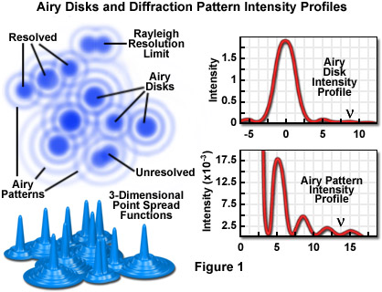
Imaging a point-like light source in the microscope produces an electromagnetic field in the image plane whose amplitude fluctuations can be regarded as a manifestation of the response of the optical system to the specimen. This field is commonly represented through the amplitude point spread function, and allows evaluation of the optical transfer properties of the combined system components. Although variations in field amplitude are not directly observable, the visible image of the point source formed in the microscope and recorded by its imaging system is the intensity point spread function, which describes the system response in real space. Actual specimens are not point sources, but can be regarded as a superposition of an infinite number of objects having dimensions below the resolution of the system. The properties of the intensity point spread function (PSF; see Figure 1) in the image plane as well as in the axial direction (Figure 3) are major factors in determining the resolution of a microscope.
It is possible to experimentally measure the intensity point spread function in the microscope by recording the image of a subresolution spherical bead as it is scanned through focus (a number of examples may be found in the literature). Because of the technical difficulty posed in direct measurement of the intensity point spread function, calculated point spread functions are commonly utilized to evaluate the resolution performance of different optical systems, as well as the optical-sectioning capabilities of confocal, two-photon, and conventional widefield microscopes. Although the intensity point spread function extends in all three dimensions, with regard to the relationship between resolution and contrast, it is useful to consider only the lateral components of the intensity distribution, with reference to the familiar Airy disk.
The intensity distribution of the point spread function in the plane of focus is described by the rotationally symmetric Airy pattern. Because of the cylindrical symmetry of the microscope lenses, the two lateral components (x and y) of the Airy pattern are equivalent, and the pattern represents the lateral intensity distribution as a function of distance from the optical axis. The lateral distance is normalized by the numerical aperture of the system and the wavelength of light, and therefore is dimensionless. Figure 1 (airy disk and intensity function) illustrates diagrammatically the formation and characteristics of the Airy disk, the related three-dimensional point spread function, and Airy patterns in the fluorescence microscope. Following the excitation of fluorophores in a point-like specimen region, fluorescence emission occurs in all directions, a small fraction of which is selected and focused by the optical components into an image plane where it forms an Airy disk surrounded by concentric rings of successively decreasing maximum and minimum intensity (the Airy pattern).
The Airy pattern intensity distribution is the result of Fraunhofer diffraction of light passing through a circular aperture, and in a perfect optical system exhibits a central intensity maximum and higher order maxima separated by regions of zero intensity. The distance of the zero crossings from the optical axis (represented by the variable n in Figure 1), when the distance is normalized by the numerical aperture and wavelength, occur at values for n of 3.8, 7.0, 10.2, 13.3....etc. When the intensity on the optical axis is normalized to one (100 percent), the proportional heights of the first four higher order maxima are 1.7, 0.4, 0.2, and 0.08 percent, respectively.
Resolution and Contrast
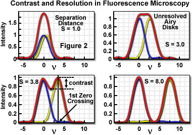
A useful approach to the concept of resolution is based on consideration of an image formed by two point-like objects (specimen features), under the assumption that the image-forming process is incoherent, and that the interaction of the separate object images can be described using intensity point spread functions. The resulting image is then composed of the sum of two Airy disks, the characteristics of which depend upon the separation distance between the two points. Figure 2 presents a representation of the lateral interaction between the intensity point spread functions (which are the Airy functions) for two point objects at various separation distances. When the two objects are widely separated, their images are easily distinguished on the basis of the variation in image intensity.
As is apparent in Figure 2, when sufficiently separated, the intensity change in the area between the objects is the maximum possible, cycling from the peak intensity (at the first point) to zero and returning to the maximum value at the center of the second point. At decreased distance in object space, the intensity distribution functions of the two points, in the image plane, begin to overlap and the resulting image may appear to be that of a single larger or brighter object or feature rather than being recognizable as two objects. If resolution is defined, in general terms, as the minimum separation distance at which the two objects can be sufficiently distinguished, it is obvious that this property is related to the width of the intensity peaks (the point spread function). Microscope resolution is directly related, therefore, to the full width at half maximum (FWHM) of the instrument's intensity point spread function in the component directions.
Some ambiguity in use of the term resolution results from the variability in defining the degree of separation between features and their point spread functions that is "sufficient" to allow them to be distinguished as two objects rather than one. In general, minute features of interest in microscopy specimens produce point images that overlap to some extent, displaying two peaks separated by a gap. The greater the depth of the gap between the peaks, the easier it is to distinguish, or resolve, the two objects. By specifying the depth of the dip in intensity between two overlapping point spread functions, the ambiguity in evaluating resolution can be removed, and a quantitative aspect introduced.
In order to quantify resolution, the concept of contrast is employed, which is defined for two objects of equal intensity as the difference between their maximum intensity and the minimum intensity occurring in the space between them. Because the maximum intensity of the Airy disk is normalized to one, the highest achievable contrast is also one, and occurs only when the spacing between the two objects is relatively large, with sufficient separation to allow the first zero crossing to occur in their combined intensity distribution. At decreased distance, as the two point spread functions begin to overlap, the dip in intensity between the two maxima (and the contrast) is increasingly reduced. The distance at which two peak maxima are no longer discernible, and the contrast becomes zero, is referred to as the contrast cut-off distance. The variation of contrast with distance allows resolution, in terms of the separation of two points, to be defined as a function of contrast.
The relationship between contrast and separation distance for two point-like objects is referred to as the contrast/distance function or contrast transfer function. Resolution can be defined as the separation distance at which two objects are imaged with a certain contrast value. It is obvious that when zero contrast exists (Figure 2(b)), the points are not resolved; the so-called Sparrow criterion defines the resolution of an optical system as being equivalent to the contrast cut-off distance. It is common, however, to specify that greater contrast is necessary to adequately distinguish two closely spaced points visually, and the well-known Rayleigh criterion for resolution states that two points are resolved when the first minimum (zero crossing) of one Airy disk is aligned with the central maximum of the second Airy disk. Under optimum imaging conditions, the Rayleigh criterion separation distance corresponds to a contrast value of 26.4 percent. Although any contrast value greater than zero can be specified in defining resolution, the 26-percent contrast of the Rayleigh criterion is considered reasonable in typical fluorescence microscopy applications, and is the basis for the common expression defining lateral resolution according to the following equation, in which the point separation (r) in the image plane is the distance between the central maximum and the first minimum in the Airy disk:
where l is the emitted light wavelength and NA is the numerical aperture of the objective.
Resolution in the microscope is directly related to the FWHM dimensions of the microscope's point spread function, and it is common to measure this value experimentally in order to avoid the difficulty in attempting to identify intensity maxima in the Airy disk. Measurements of resolution utilizing the FWHM values of the point spread function are somewhat smaller than those calculated employing the Rayleigh criterion. Furthermore, in confocal fluorescence configurations, pointwise illumination scanning and pointwise detection are employed, so that only the fluorophores in the shared volume of the illumination and detection point spread functions are able to be detected. The intensity point spread function in the confocal case is, therefore, the product of the independent illumination intensity and detection intensity point spread functions. For confocal fluorescence, the lateral (and axial) extent of the point spread function is reduced by about 30 percent compared to that in the widefield microscope. Because of the narrower intensity point spread function, the separation of points required to produce acceptable contrast in the confocal microscope is reduced to a distance approximated by:
If the illumination and fluorescence emission wavelengths are approximately the same, the confocal fluorescence microscope Airy disk size is the square of the widefield microscope Airy disk. Consequently, the contrast cut-off distance is reduced in the confocal arrangement, and equivalent contrast can be achieved at a shorter distance compared to the widefield illumination configuration. Regardless of the instrument configuration, the lateral resolution displays a proportional relationship to wavelength, and is inversely proportional to the objective lens numerical aperture.
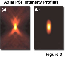
As noted previously, lateral resolution is of primary interest in discussing resolution and contrast, although the axial extent of the microscope intensity point spread function is similarly reduced in the confocal arrangement as compared to the widefield fluorescence configuration. Reasonable contrast between point-like objects lying on the optical axis occurs when they are separated by the distance between the central maximum and the first minimum of the axial point spread function component. Presented in Figure 3 are the axial intensity distributions for a typical widefield (Figure 3(a)) and confocal (Figure 3(b)) fluorescence microscope. Note the dramatic reduction in intensity of the "wings" in the confocal distribution as a function of distance from the central maximum.
A variety of equations are presented in the literature that pertain to different models for calculating axial resolution for various microscope configurations. The ones most applicable to fluorescence emission are similar in form to the expressions evaluating depth of field, and demonstrate that axial resolution is proportional to the wavelength and refractive index of the specimen medium, and inversely proportional to the square of the numerical aperture. Consequently, the numerical aperture of the microscope objective has a much greater effect on axial resolution than does the emission wavelength. One equation commonly used to describe axial resolution for the confocal configuration is given below, with h representing the index of refraction, and the other variables as specified previously:
Although the confocal microscope configuration exhibits only a modest improvement in measured axial resolution over that of the widefield microscope, the true advantage of the confocal approach is in the optical sectioning capability in thick specimens, which results in a dramatic improvement in effective axial resolution over conventional techniques. The optical sectioning properties of the confocal microscope result from the characteristics of the integrated intensity point spread function, which has a maximum in the focal plane when evaluated as a function of depth. The equivalent integral of intensity point spread function for the conventional widefield microscope is constant as a function of depth, producing no optical sectioning capabilities.
Practical Factors Influencing Contrast
The importance of confocal microscopy in current biological and biomedical research results largely from the optical sectioning capability that enables the three-dimensional analysis of thick specimens such as those encountered in studies involving living cells and tissues. The optical sectioning properties result from the use of point-like illumination and detection configurations that restrict the relevant confocal observation volume to the overlap region of the illumination and detection volumes. Various strategies are employed to reduce this volume in an attempt to increase resolution of features of interest. Conventional Abbe theory describes the interaction of the parameters that can be modified to improve lateral resolution, including decreasing the wavelength of the incident light, increasing the refractive index of the specimen medium, and increasing the acceptance angle (numerical aperture) of the optical system. The first two of these are often restricted by the requirements of a given experiment with respect to the fluorophores that can be employed and by the need to maintain viability of the specimen.
Even with higher numerical aperture objectives, the use of confocal pinholes restricts the illumination and detection light paths to a much smaller portion of the maximum solid angle of the optical system, resulting in elongation of the point spread function along the optical axis. Additional research effort has led to a number of experimental techniques for reducing this restriction on axial resolution, as well as the effects of various other factors, such as refractive index mismatches, which introduce optical aberrations. Among the approaches being utilized to minimize this problem is the use of high numerical aperture water immersion objectives.
The significance of the host of practical limitations to achieving ideal optical performance is that the classical Abbe resolution calculations should not be misunderstood to describe the resolution of the microscope. The resolution predicted by the diffraction limit pertains to optimum conditions, including an unlimited signal-to-noise ratio. Fluorescence microscopy is limited in practice by low photon yield, and requires a ratio of excitation to emitted photons that typically ranges in the millions. Because resolution, even under high illumination levels, requires a certain contrast level, and contrast is affected by the ratio of signal to noise, the contrast level attained in practice depends ultimately on the number of photons detected. The resolution predicted by diffraction limits is never achieved in fluorescence observations of biological material, and for performance to be maximized the number of photons detected must be optimized at every stage in the imaging process.
In addition to the number of photons collected and various optical aberrations, the sampling process itself, which is a fundamental feature of digital microscopy, plays a role in determining contrast, and therefore resolution, in the fluorescence confocal microscope. As stated previously, the fact that digital confocal images must be not only recorded, but processed and displayed within discrete picture elements introduces imaging variables that may be unfamiliar to microscopists that are new to digital imaging. Furthermore, the pixelation, or division of an image into finite picture elements, takes place at several stages of the imaging process, and these must interact with each other to transfer image information from the specimen to the final visual image display. The possibility of mismatches among these discrete elements at the various stages is another factor that potentially limits image contrast and resolution.
The resolution imposed by the microscope optical system at the specimen level is sometimes described on the basis of the resel, which is the smallest optically resolvable element. Depending upon the criterion utilized to define a detectable intensity difference between two elements, the size of the resel can correspond to the Rayleigh limit, the Sparrow limit, or another arbitrary definition. The effect of pixelation, or digitization, is initially manifested in the imaging sequence at the optical resolution level, through the sampling of the Airy patterns that correspond to point-like features in the specimen. Partitioning, or pixelation, also takes place at the display stage of the imaging process, and differences in the use of terminology in the published literature can lead to confusion in discussing the digitization process occurring at various stages throughout the imaging sequence. The term resel refers specifically to the smallest area of the specimen (object) that can be distinguished from neighboring areas, without regard to its subsequent detection, processing, or display. In three-dimensional confocal imaging, a volume resolution element is sometimes referred to as a voxel, although there is no reason to restrict the concept of the resel to two dimensions, and the term may be used to describe the minimum spatially-resolved element (in two or three dimensions) at the specimen, determined by the optics of the microscope system.
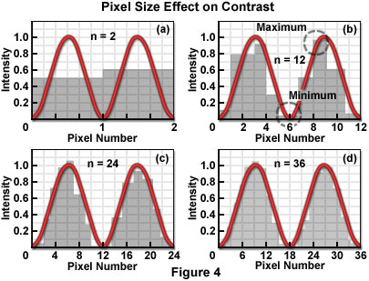
Figure 4 illustrates the mechanism by which the process of sampling the intensity of closely spaced Airy patterns reduces image contrast. The Airy pattern is generally assumed to be a smooth continuous function described by an infinite number of samples (or data points), as shown in the typical analog representation of the intensity variation across the pattern. When considered as continuous functions, the Airy patterns exhibit their full intensity variations and produce the maximum theoretical contrast for a given separation distance. If divided into a finite number of measurement points or areas, by a scanner or digital imaging device, for example, the smooth curves are transformed into a series of intensity values, each of which can be stored in a computer memory location. By sampling at discrete intervals, the possibility is introduced of overlooking the positions that include the minimum and maximum of the function.
Each pixel averages, or summarizes, the intensity response of the optical system within a specified area. Since the Airy function zero crossings occur at points, not areas, a pixel value cannot be zero for any finite pixel size. Similarly, the measured maximum value of the intensity peaks is reduced by the area averaging, and the combined effect of increasing the minimum and decreasing the maximum is to reduce the contrast. Consequently, the cut-off distance is increased and the resolution decreased (for any contrast criterion) by the pixelation process. Furthermore, if pixel size relative to the resel size is too large, ambiguity is introduced in the positions of the minima and maxima of the intensity response in the image plane. The severity of the effect of partitioning the intensity into pixels depends directly upon the size of the pixel with respect to the Airy disk diameter, which in turn is related to the resel size imposed by the system optics at the wavelength of the image-forming light.
It is unavoidable that any resolution inherent in the optical system, which is not sufficiently sampled by the detector, is lost. The effect of pixelization is minimized as more pixels are utilized to describe the intensity variations. Several detector designs acquire pixelated data as an intrinsic property of the detector (CCD cameras, for example), while others require a continuous analog signal to be digitized by an analog-to-digital converter or similar digitizer, following detection. The line scan of confocal laser scanning systems utilizing a single detection channel operate in this manner. The relationship of the pixel size to the diameter of the Airy disk determines the number of pixels that are required to sample two adjacent Airy disks to achieve a certain contrast. The challenge in digital microscopy is to manage the relationship among optical resolution, sampling interval in the spatial domain, and the pixel dimensions of the display device in order to maximize the capture and display of true specimen information, while minimizing visual artifacts that may be introduced by interactions among the various sampling (partitioning) stages.
An additional factor of practical interest in determining the contrast and resolution of captured images is the intensity resolution, which governs the brightness value that is assigned to each image pixel. By analogy to the resel, the size of which is determined by the optical characteristics of the system, the minimum detectable difference in intensity that can be resolved depends upon electronic properties of the detector, in particular its signal-to-noise ratio. When transferred to the image-output stage, each pixel's brightness is described by a gray level, and the accuracy with which the brightness is represented depends upon the relationship between the number of gray levels utilized and the smallest detectable intensity difference measured by the detector. When stored by the computer, each pixel corresponding to a spatial location in the image has an associated intensity value ranging from 0 to 255 for 8-bit storage (256 gray levels). In confocal microscopy, the use of more than 256 gray levels is seldom justified by the detection resolution, although there may be some value in discriminating more intensity levels for certain data processing algorithms.
It is important to recognize that pixelation at the image display stage is not unique to digital imaging. Some form of "granularity" is inherent in every type of image presentation, and manipulations of the size and organization of the grains are utilized to represent the required range of gray levels. Photographic film has silver grains of various sizes, television displays are arrays of discrete horizontal lines, each of which displays intensity variations based on electronic bandwidth, and half-tone printing techniques group black and white dots into pixels of various sizes to simulate continuous tonal variations. Video monitors are able to vary the intensity of each displayed dot and achieve some tonal variation even while utilizing one dot per pixel. However, in order to represent a sufficient number of gray levels to produce the visual effect of continuous-tone images, or to display color variations, a number of dots must be assigned to represent each pixel. Film-based photographic methods assign multiple silver grains to each image resel in order to provide an adequate range of intensities necessary to give the appearance of continuous tonal variation. In all of these methods, as more fundamental dots or image elements are grouped to achieve greater tonal range, the appearance of the image becomes more "grainy", with the effect of reducing apparent resolution. The inverse relationship between pixel size and the ability to display greater gray-scale range must be considered and balanced according to the imaging requirements.
The fact that all digital confocal microscopy images are acquired, processed, and displayed in the realm of discrete partitions, or pixels, as opposed to being treated as a continuous representation of the specimen data is not a problem of fundamental significance, but rather is a practical matter of imaging technique. As long as the microscope is operated in accordance with applicable sampling theory, which governs the sampling interval in space or time that is required to reproduce features of interest with sufficient contrast, there is no significant limitation. The sampling criterion most commonly relied upon is based on the well known Nyquist Theorem, which specifies the sampling interval required to faithfully reconstruct a pure sine wave as a function of its frequency. The problem in practice is that use of the zoom magnification control on typical confocal microscopes can easily be misused in a manner that violates the Nyquist criterion.
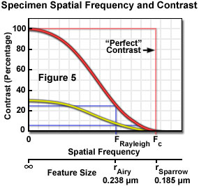
The application of Nyquist sampling theory is usually explained by considering the specimen features in the domain of spatial frequency rather than object size. In effect, the number of objects per spatial unit (the frequency) is the inverse of object size and emphasizes the importance of the spacing between specimen features in image formation. Use of the spatial frequency domain is consistent with the practice of evaluating performance of optical systems on the basis of their ability to maintain contrast (and visibility) when transferring image information of different frequencies. All optical systems degrade contrast in the imaging process, and this effect is more severe for higher spatial frequencies (small spacing) than for lower frequencies (larger spacing). The contrast transfer function (CTF) of an optical system is constructed by plotting the measured contrast in an image of test patterns consisting of periodic arrays having alternating dark and light bars at a range of frequencies, or spacing intervals. Figure 5 illustrates a hypothetical CTF for an optical system, and includes curves for the system response to a test target having black and white bars (100 percent contrast), and to a target made up of gray and white bars yielding only 30 percent contrast.
Examination of the contrast transfer curves of Figure 5 clearly illustrates the interdependence of resolution and contrast, and the problem of some common assumptions that are made, which treat resolution as a constant of instrument performance. Resolution is a somewhat arbitrary variable that is meaningful only when considered within the framework of other related factors. When defined as the highest spatial frequency that produces a certain contrast, it is easily assumed that any features having frequencies within the stated resolution limit are equally visible, when in fact specimen features that are originally of high contrast will be more clearly visible than those of lower contrast at every frequency up to the contrast cut-off frequency. The curves (Figure 5) illustrate that specimen features initially having only 30-percent contrast due to staining characteristics or other factors, would not maintain the Rayleigh-specified 26-percent contrast level at spatial frequencies anywhere near the theoretical limit, which assumes equal contrast at all frequencies up to the resolution limit. The contrast of small features that are slightly within the resolution limit produce contrast much lower than that of larger features after each has been degraded by the transfer function of the imaging system.
The visibility of specimen features in the microscope image depends upon the contrast of the features with respect to their surroundings, the performance of the optical system as reflected in the contrast transfer function, signal-to-noise statistics, and the manner in which the signal is sampled for digitization. Nyquist found that in order to faithfully reconstruct a pure sine wave, it must be sampled at least twice during each cycle of the wave, or at two-times the temporal frequency. The frequencies of interest in imaging are of a spatial nature, but the Nyquist theorem is equally applicable to this type of data. The minimum sampling frequency employed in microscopy imaging applications is usually 2.3 times the maximum frequency to be reconstructed. The value of 2.3 is used (instead of 2, as suggested by Nyquist) as a practical matter in order to compensate for the low-pass filtration that is required for perfect image reconstruction in real optical systems.
Low-pass filtration that is applied to the sampled data before the image is reconstructed is analogous to the "filtration" done by the eye and brain to smooth pixelated data such as half-tone images, or to moving farther away from a display such as a large screen television in order to eliminate visible scan lines. Low-pass filtration performs removal of sampling artifacts that are extraneous to the data, and helps to make the image appear continuous. An ideal filter would permit sampling at 2-times the highest frequency, but since no such devices exist, experience has led to the generalization that sampling at 2.3-times the highest frequency is sufficient to accommodate the performance of real filters (often an integrator in digital-to-analog converters).
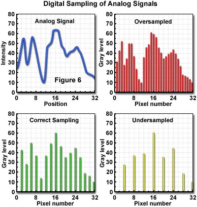
In practical operation of the microscope, there is often some uncertainty in estimating the highest frequency that should be of concern in the specimen. Many specimens have sharply defined edges, and numerous minute features that contribute extremely high-frequency components to the signal. The Airy intensity distribution function or Gaussian distribution imposed by optical elements blurs these components to the extent that detail appears only within the optical resolution limit. Failure to sample all of the frequency components below the limit can produce image errors, although it is unnecessary to sample at the higher frequencies, which will no longer carry specimen information following optical transfer (see Figure 6). In some cases, specimens should be sampled at more than 2.3-times the highest information frequency to allow for the possibility that the highest frequency was misjudged. In the confocal laser scanning microscope, the highest frequency to be sampled (f) is imposed by the optical system, and for a particular resolution specification:
In order to preserve all of the information transferred by the optical system to the sampling (digitizing) stage of the microscope, having a contrast transfer function such as that illustrated in Figure 5, the pixel size must be smaller than the inverse of 2.3-times the cut-off frequency (fcut-off):
An accurate representation of specimen features, within the limits imposed by the experiment, requires use of a spatial sampling frequency and electronic properties, such as bandpass, which are matched to the optical resolution of the system. In the confocal microscope, the optical resolution (the resel size) is primarily determined by the wavelength of the light and the numerical aperture of the objective. The zoom control on the microscope provides the capability to match the pixel size to the optical characteristics, and to meet the Nyquist criterion of acquiring samples at a minimum of twice the highest spatial frequency of the specimen signal. In general, the zoom control varies the size of the area scanned on the specimen, but does not change the number of pixels sampled. Consequently, pixel size varies inversely with zoom factor. There is only one optimal zoom setting for a particular combination of wavelength, numerical aperture, and objective magnification: the one that provides a pixel size that matches the Nyquist criterion when referenced to the specimen space. At other than the optimum zoom setting, two different imaging problems are created, depending upon whether the pixel size results in oversampling or undersampling (Figure 6) of the data.
When operating at zoom settings of the microscope that are higher than that corresponding to the Nyquist condition, smaller pixels are generated at the specimen, oversampling the data within the reduced scanning area. Sampling with smaller pixel size than that required by the optical resolution not only subjects the specimen to more severe photobleaching than is necessary, but also decreases the area that can be scanned in a given period of time. It is sometimes considered useful to sample a specimen feature at frequencies much higher than that corresponding to the Nyquist limit, in order to obtain information about the position of a feature. Operating in this manner produces a condition referred to as hyper-sampling, in which the position of an unresolved object may be located with greater precision than afforded by the optical resolution of the microscope. Although no details about the specimen feature are provided beyond that allowed by the resel dimensions, its location can be determined from the intensity distribution of the blurry image. Provided that the feature is sampled by a large number of pixels, and it is stable to the high photon flux that this oversampling implies, the centroid of the spot identifies its location within the limits imposed by the signal noise.
A different type of problem results from undersampling of the specimen data. This situation is caused, as is the case for oversampling, by a mismatch in the partitioning mechanisms of the imaging sequence. The mismatch occurs between sampling frequency and resel size (resolution), and involves spatial frequencies in the data that are higher than can be accurately represented by the sampling rate. Undersampling typically occurs at lower microscope zoom settings for which the pixel size is larger than that specified by the Nyquist criterion. In addition to smaller features being completely missed by the sampling, other features may appear in the image that are not present in the specimen. This phenomenon is possible due to a process known as aliasing, in which specimen features take on an entirely different character in the image than they actually have in the specimen. In effect, they appear under an "alias", or false identity and are often masqueraded as spatial frequencies that do not exist in the specimen.
The process is illustrated in Figure 7 in which specimen features of 3-per-micrometer frequency are sampled at a frequency of 2-per-micrometer. The sample partitioning misses entire cycles of the specimen data, and outputs a 1-per-micrometer signal that does not exist in the specimen. The aliased image results from the undersampling mismatch between the resolved data and the detector characteristics. When actual features are missed by so-called "blind spots" produced by too-large pixel size, the aliasing may cause features to appear that are larger, smaller, or in different locations than they are in the specimen. Once the sampling has occurred, there is no way to determine which image features are real and which are artifacts.
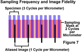
In a situation such as the one illustrated in Figure 7, since specimen features of this size cannot be accurately rendered at the chosen sampling rate, either the sampling rate must be increased, or some form of filtration should be employed to eliminate frequencies that are beyond those that can be dealt with by the system (those exceeding the Nyquist limit). Sampling at greater than 6 cycles per micrometer would satisfy the Nyquist criterion, and accurately reproduce the specimen features, but if this is not possible, the most practical solution in most cases is to adjust the microscope zoom setting to provide a match between the sampling and resolution mechanisms. If a sufficient number of pixels is not achievable for proper representation of the specimen features, the resolution should be limited, or degraded, optically and/or electronically before partitioning of the data by sampling.
A popular method of limiting optical resolution is to employ smaller numerical aperture optical components, or to underfill the rear focal plane of the objective to reduce its effective numerical aperture. The chief disadvantage of this approach is that it reduces light collection efficiency, and the consequent increase in specimen exposure time (for image acquisition) risks greater damage to sensitive specimens. Another mechanism of degrading resolution to match sampling properties is to utilize larger pinhole diameters (or other optical methods) to increase the effective size of the source disk beyond the diffraction-limited spot size. This technique has the advantage of degrading both lateral and axial resolution in a linear manner, while numerical aperture changes affect axial resolution quadratically. In either case, the confocal microscope retains its optical sectioning capabilities and characteristic sampling flexibility. Additionally, it is commonly suggested that when detection systems, such as single-channel photomultiplier tubes are used (in which the pixelization of signal is not inherent to the detector), the sampling resolution should be degraded electronically as well. For a given sampling rate, an integrator can be employed ahead of the analog-to-digital converter to limit sampling of the signal voltage to the Nyquist-specified rate.
It is important to be able to operate the microscope with spot sizes consistent with the specimen and fluorophore properties, and appropriate to the requirements of the experiment. Ideally, the instrument should enable operation at both the diffraction-limited configuration, and at larger spot sizes. There are a number of experimental situations in which it is desirable to intentionally operate the microscope at less than its diffraction-limited resolution by breaking the rules pertaining to focal spot size, pinhole diameter, and sampling frequency, but the operator should always be aware of the circumstances justifying these deviations.
Contributing Authors
Kenneth R. Spring - Scientific Consultant, Lusby, Maryland, 20657.
Thomas J. Fellers and Michael W. Davidson - National High Magnetic Field Laboratory, 1800 East Paul Dirac Dr., The Florida State University, Tallahassee, Florida, 32310.
